Project Quiver Dev Kit Engineering Report
Executive Summary
The Quiver Dev-Kit is the first commercial release of Project Quiver, an open source heavy lift quadcopter platform developed by Arrow Air. This report documents the technical work carried out from September 2025 through early 2026 to bring the PT3 prototype to a stable developer release. It is a delta document. The structural modifications, electronics revisions, software development, and obstacle avoidance integration covered here represent changes from PT3. A Platform Engineering Report providing a complete reference for the Quiver platform as a whole is planned as a separate document.
The structural modifications centered on weight reduction and weatherproofing. Plate thinning succeeded on the upper airframe but failed under payload on the lower frame, an outcome that FEA did not predict and that a 7 kg payload flight test was required to surface. The final configuration retains thinned upper plates and keeps the lower frame and battery bay walls at original thickness. Weatherproofing was validated to IP53 through garden hose testing and confirmed suitable for light rain operations.
Electronics revisions focused on reliability and tighter integration of the companion computer and networking hardware. The four-PCB architecture received improved power protection, a dedicated backup supply for the flight controller, and a vibration isolation mount that decouples the PCB stack from propulsion vibration. Copper bus bars replaced cabling on the battery board for high current capacity, and surface mounted standoffs now secure the Raspberry Pi and Ethernet switches directly to the Main PCB. For convenience, various connectors were updated on the PCBs to match the default on the system peripherals.
Obstacle avoidance integration combined an RPLidar S2L and NanoRadar MR82 with a custom ArduPilot firmware build running the BendyRuler algorithm. Software in the loop (SITL) simulation established safe operating parameters ahead of field testing, which is structured across four phases and has not yet begun. An intermittent LiDAR dropout under flight conditions is under active investigation.
The software work produced two things: Quiver Hub, a web application with five core operator applications and an extensibility framework for custom payload integrations, and the Quiver SDK, which runs two persistent services on the Raspberry Pi for telemetry relay and job execution. As a first integration, point cloud data from an RPLidar payload was streamed through the companion computer to Quiver Hub and rendered in the browser in real time, confirming the data path from onboard sensor to operator display works as intended.
With Remote ID integration validated in April 2026 via DroneCAN, endurance flight testing is the remaining prerequisite before first external shipments. Per-operator configuration of the UAS ID and operator credentials is required before each unit ships. EASA C3 certification was deferred based on cost relative to the current development stage.
Evolution of Project Quiver
Prototype Comparison
| Feature | PT1 | PT2 | PT3 | Dev-Kit |
|---|---|---|---|---|
| Airframe Material | Aluminum/CF/3D prints | Aluminum/CF/3D prints | Aluminum/CF/3D prints | Aluminum/CF/3D prints (upper plates thinned to 1 mm) |
| Weatherproofing | No | No | Partial (untested) | IP53 validated |
| Enclosure | Standard | Standard | Standard | Modified: LiDAR mount, steel latches, module plate |
| Landing Gear | Fixed | Fixed | Detachable (prototype) | Detachable 30 mm (production, RJX Hobby) |
| Payload Interfaces | One | One | Three (C1/C2/C3) | Three (C1/C2/C3) |
| GNSS System | Basic | Initial RTK | Holybro F9P Rover Mini & Mateksys M9N-G4-3100 | Holybro F9P Rover Mini & Mateksys M9N-G4-3100 |
| Flight Controller | Pixhawk 6X | Mateksys H743 | Pix32 V6 | Pix32 V6 |
| PCB Strategy | Repurposed from Feather Testbed | Custom main PCB | Multiple custom PCBs (first revision) | Revised PCBs: JST-GH connectors, 5V backup, vibration mount |
| Battery Management | Contactor controlled by Arduino | SSR & Pre-charge | Battery PCB w/ temp monitoring and kill switch | Battery PCB: upgraded MOSFETs, copper bus bars |
| PCB Vibration Isolation | None | None | None | Rubber dampener mount (3D printed adapter plate) |
| Altimeter Sensors | Radar altimeter | LiDAR | Ainstein US-D1 Radar, Benewake TF03-180 LiDAR | Same sensors, redesigned X-pattern mount |
| Communication | CAN, Serial, Analog | CAN, Serial, Analog | CAN, Serial, Analog, Ethernet | CAN, Serial, Analog, Ethernet |
| Raspberry Pi Integration | None | Optional | Optional | Integrated on Main PCB (SMD standoffs) |
| Obstacle Avoidance | None | None | Sensors selected | RPLidar S2L + NanoRadar MR82, BendyRuler |
| Software Platform | None | None | None | Quiver SDK + Quiver Hub |
| Remote ID | None | None | None | DroneCAN integration validated; per-operator configuration required |
| Transport Case | None | None | None | Pelican 1640 w/ custom laser cut foam |
| Testing Sites | US | Germany | US & Germany | US & Germany |
Technical Improvements
This portion of the report highlights and summarizes the modifications introduced for the Dev-Kit. For additional details, refer to the individual information notes linked in the Appendix.
Airframe & Structural Improvements
The Dev-Kit structural design is an evolution of the PT3 airframe, preserving core geometries while incorporating modifications to resolve limitations observed during PT3 operations. These enhancements address environmental sealing, increased payload mounting provisions, structural mass optimization, and additional cable routing provisions.
Weatherproofing
The Dev-Kit was designed and validated to IP53, covering protection from dust sufficient to interfere with operation and from water sprayed at any angle. Validation was performed by spraying the sealed enclosure with a garden hose across multiple angles, with Julius conducting the primary water testing in February 2026. Seven primary ingress points were identified and addressed:
| Area | Solution |
|---|---|
| Lid to enclosure gap | Silicone sealing strip (groove and lip design) |
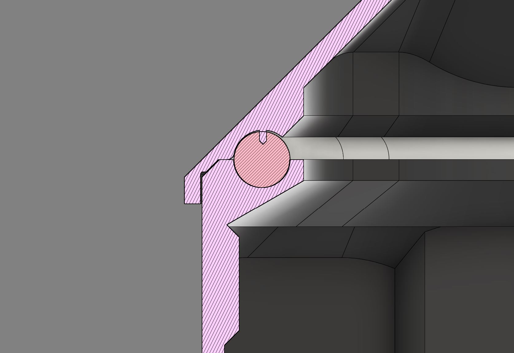
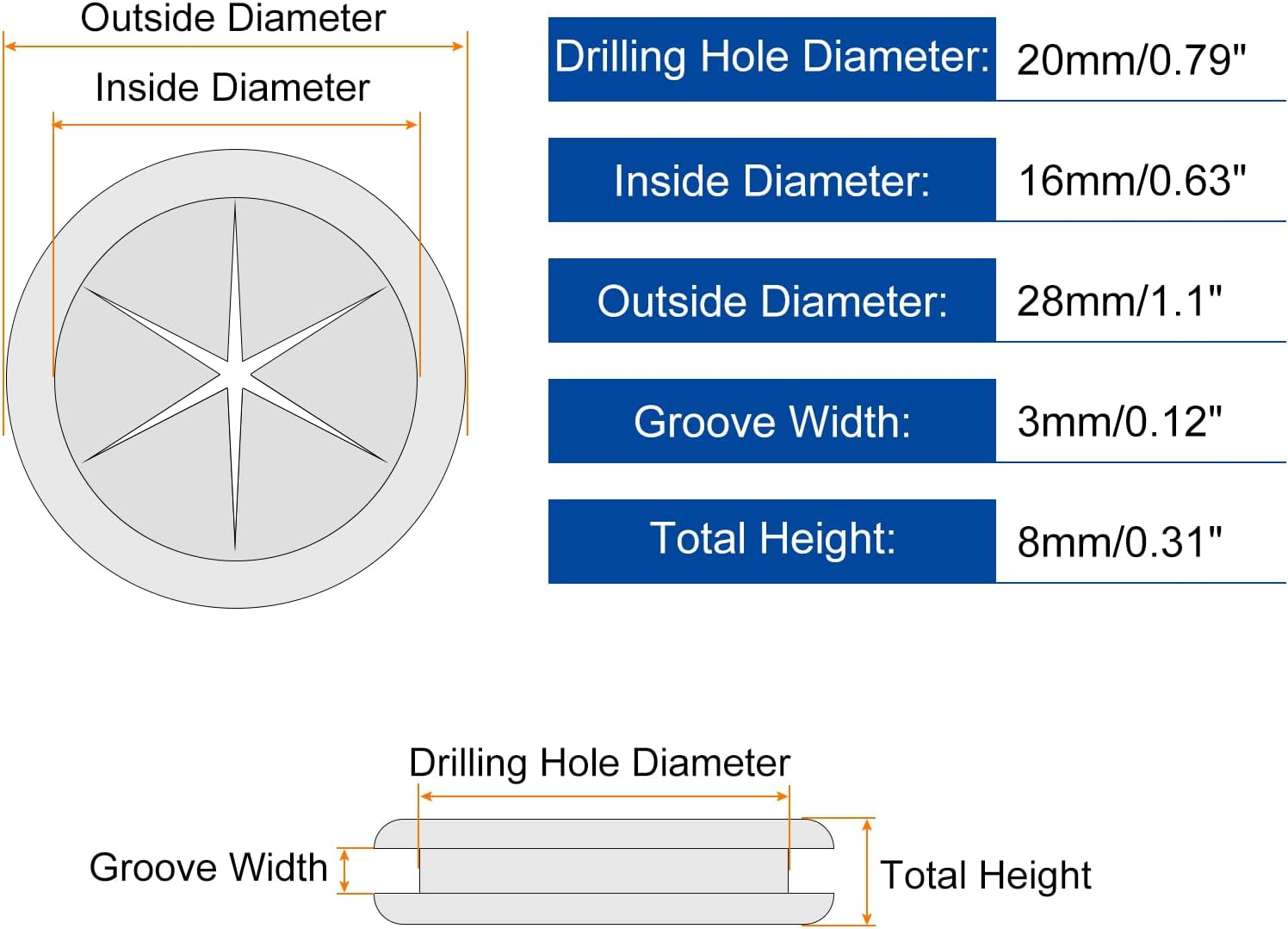
| ESC cable holes | Rubber grommets |
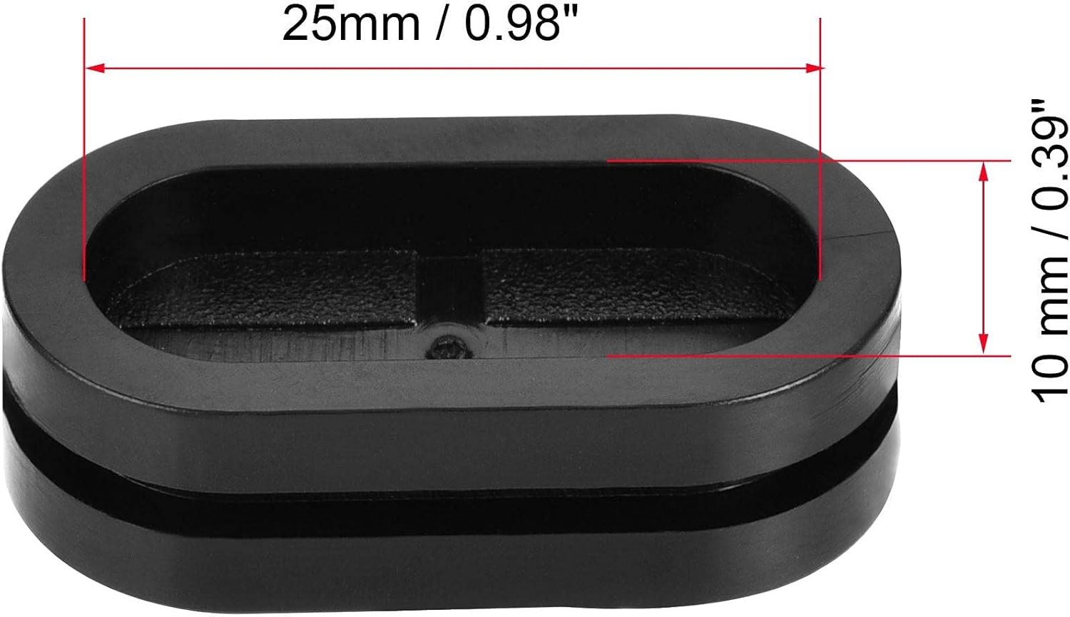
| Battery wall rectangular holes | Oval rubber seal, cut to pass cables |
| Plate to enclosure gap | No action required. Silicone can be applied if needed. |
| Front side cable entrance | Entrance removed from the enclosure |
| Battery PCB compartment gap | Removable silicone sealant (e.g., Würth 08933311) |
| LiDAR cable entrance hole | Adhesive silicone sealant (e.g., Würth 08901003) |
For the lid seal specifically, two validated solutions were developed in parallel:
- Liquid silicone gasket (Version 1): A groove on the lid is filled to half depth with 30A hardness liquid silicone. Once cured, it forms a custom fitted waterproof gasket.
- Foam strip seal (Version 2): An 8 mm diameter silicone foam strip (Uxcell) is inserted into a groove on the main enclosure body to act as a compression seal.
Julius's foam strip seal was adopted as the primary design following water testing in February 2026.
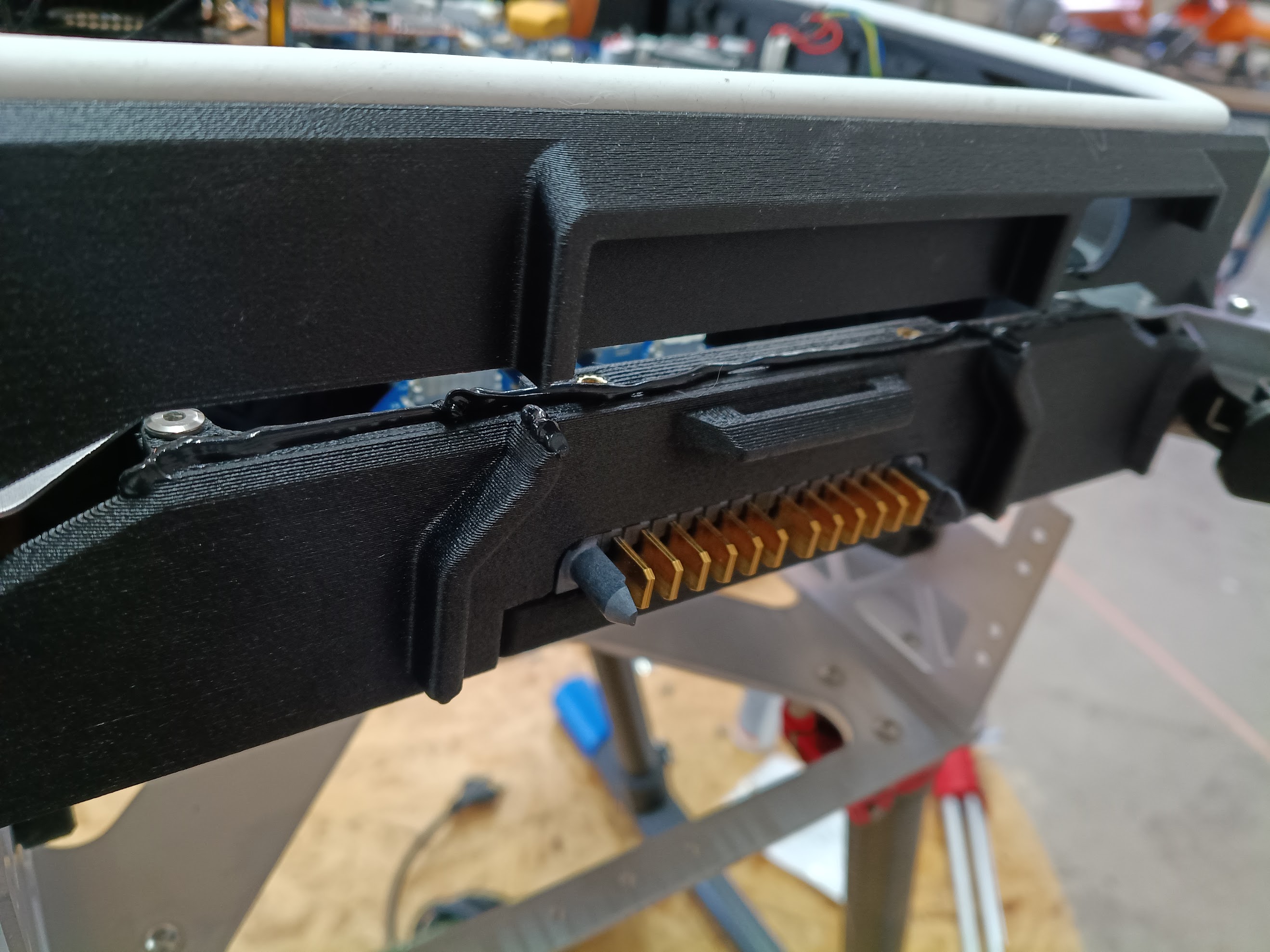
[!NOTE] A short flight in light rain is feasible with these sealing changes applied. The battery connector remains a known ingress risk at the IP53 boundary.
| Lid seal — foam strip | ESC cable grommets | Battery wall seal | Battery PCB gap |
|---|---|---|---|
 |  |  |  |
Main Enclosure Modifications
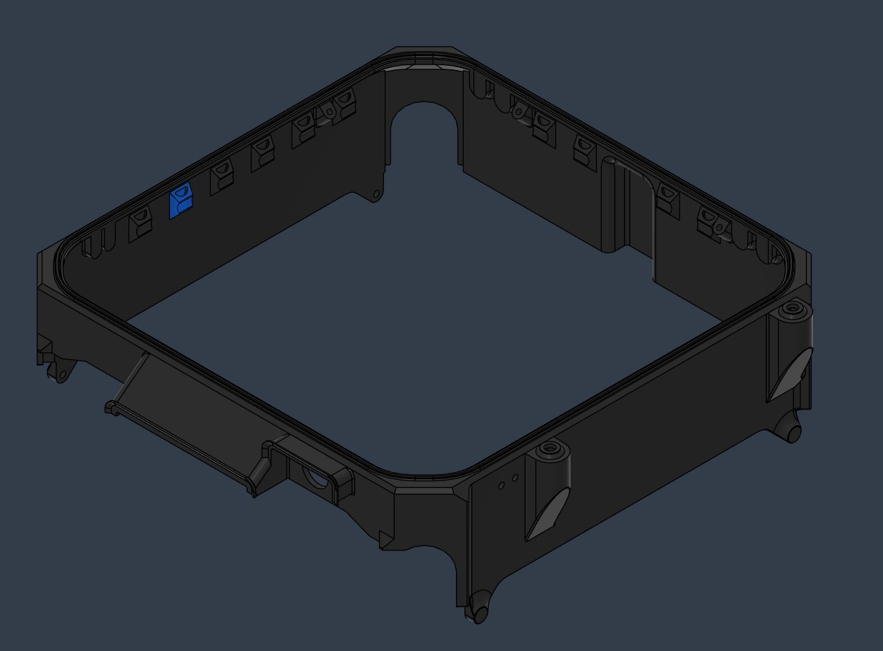
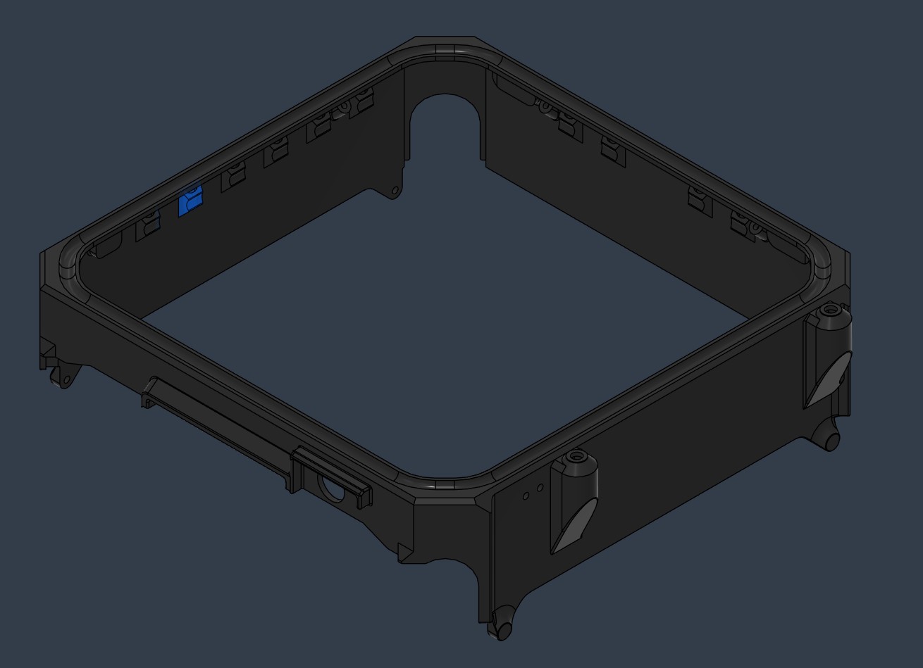
The main enclosure and cockpit lid were comprehensively redesigned to support the Dev-Kit's expanded sensor suite, improved serviceability, and weatherproofing requirements. Two design versions were developed (Version 1 and Version 2) and are available for 3D printing.
| Version 1 | Version 2 |
|---|---|
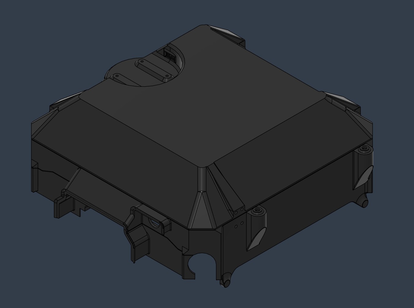 | 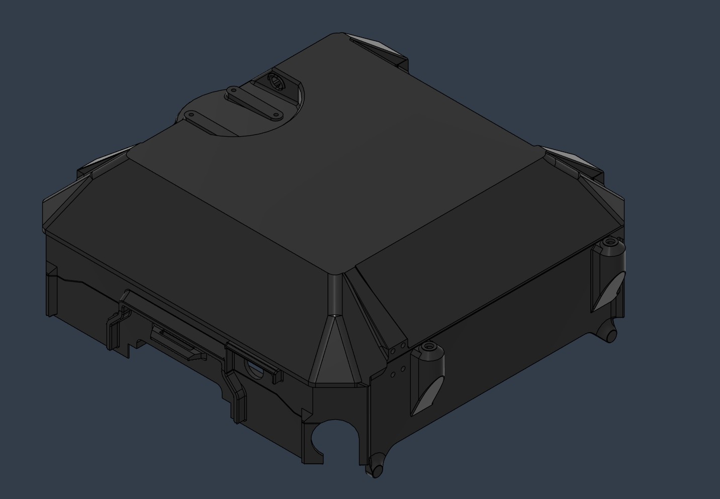 |
 |  |
Cable Anchors
New curved cable anchors compatible with zip ties and large cables were integrated throughout the enclosure interior. The anchor geometry is optimized for supportless 3D printing. The total number of anchors exceeds current requirements, providing spare capacity for future wiring additions.
| Version 1 | Version 2 |
|---|---|
 |  |
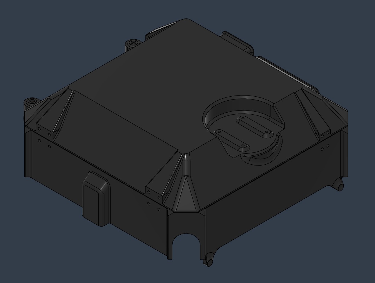
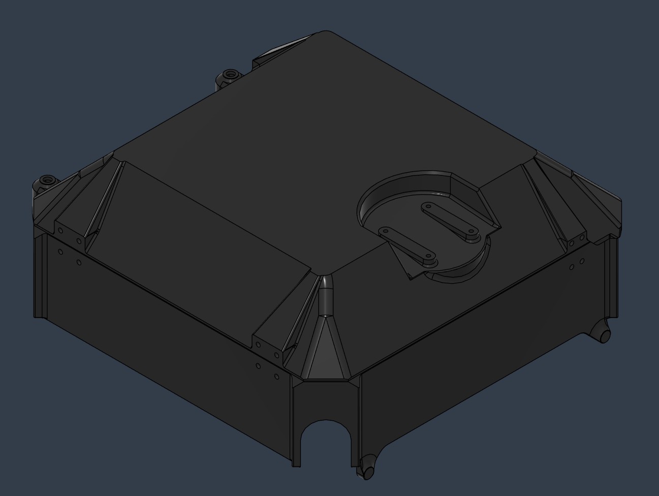
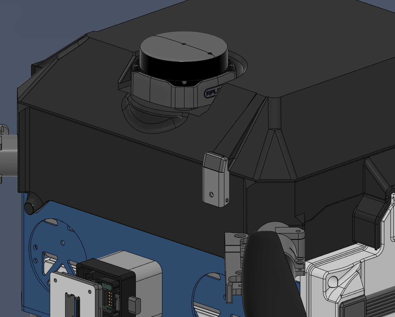
Embedded LiDAR Mount
The cockpit lid incorporates a dedicated mounting slot for the SLAMTEC RPLidar S2L 360° LiDAR module. The slot minimizes the module's height profile above the lid while preserving the full optical path of the laser beam. Drainage gaps and cable outlets are sized to pass the full LiDAR electrical connector and are compatible with sealant application.
| Version 1 | Version 2 |
|---|---|
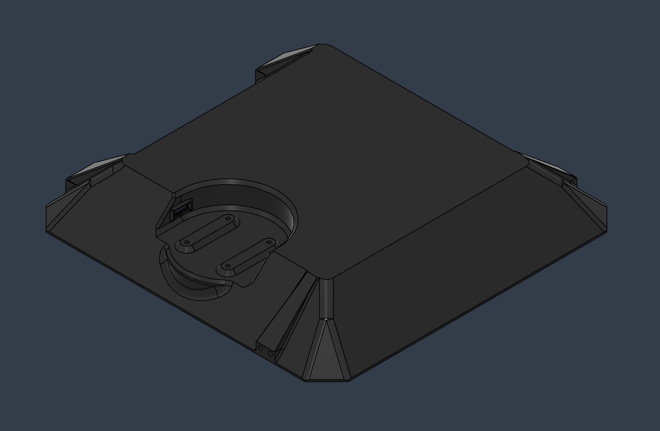 | 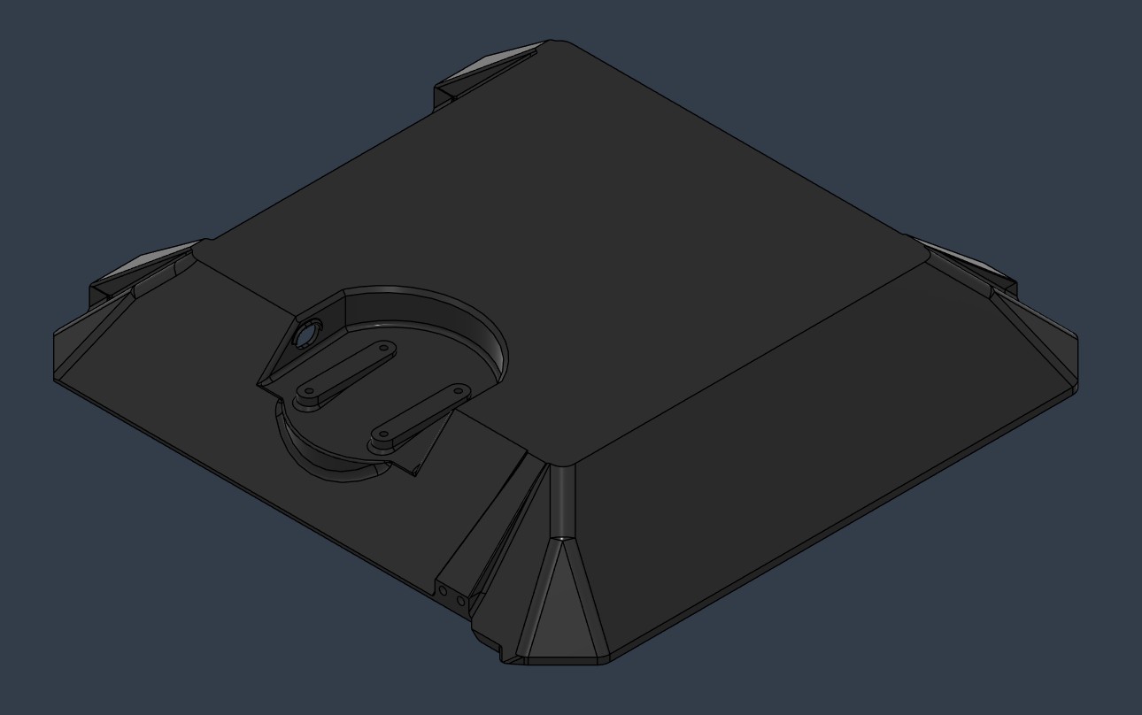 |
Cockpit Latch Replacement
The original 3D printed latches were replaced by stainless steel draw latches (McMaster-Carr 6082A11) on both sides of the lid for improved long term reliability.
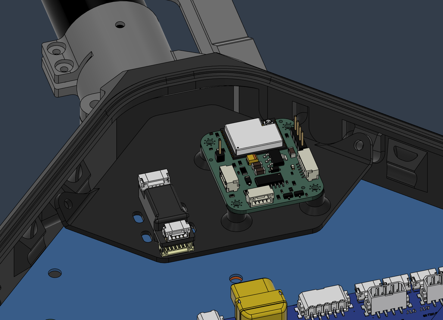
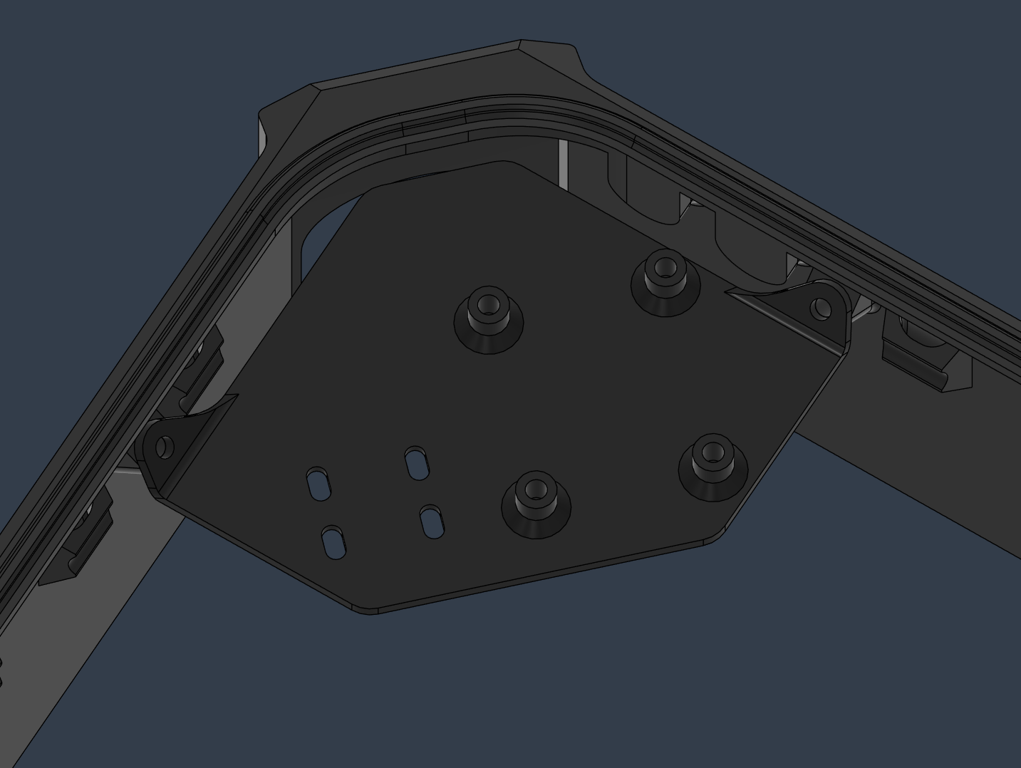
Module Mounting Plate
A triangular floating mounting plate was added to the main enclosure's inner corner to secure the Ethernet adapter and Remote ID beacon module. The plate is interchangeable between left and right sides of the aircraft (note: not interchangeable between Version 1 and Version 2 due to geometry differences). Screw insert bases are angled at 45° for maintenance access and supportless 3D printing.
| Assembly view | Isolated view |
|---|---|
 |  |
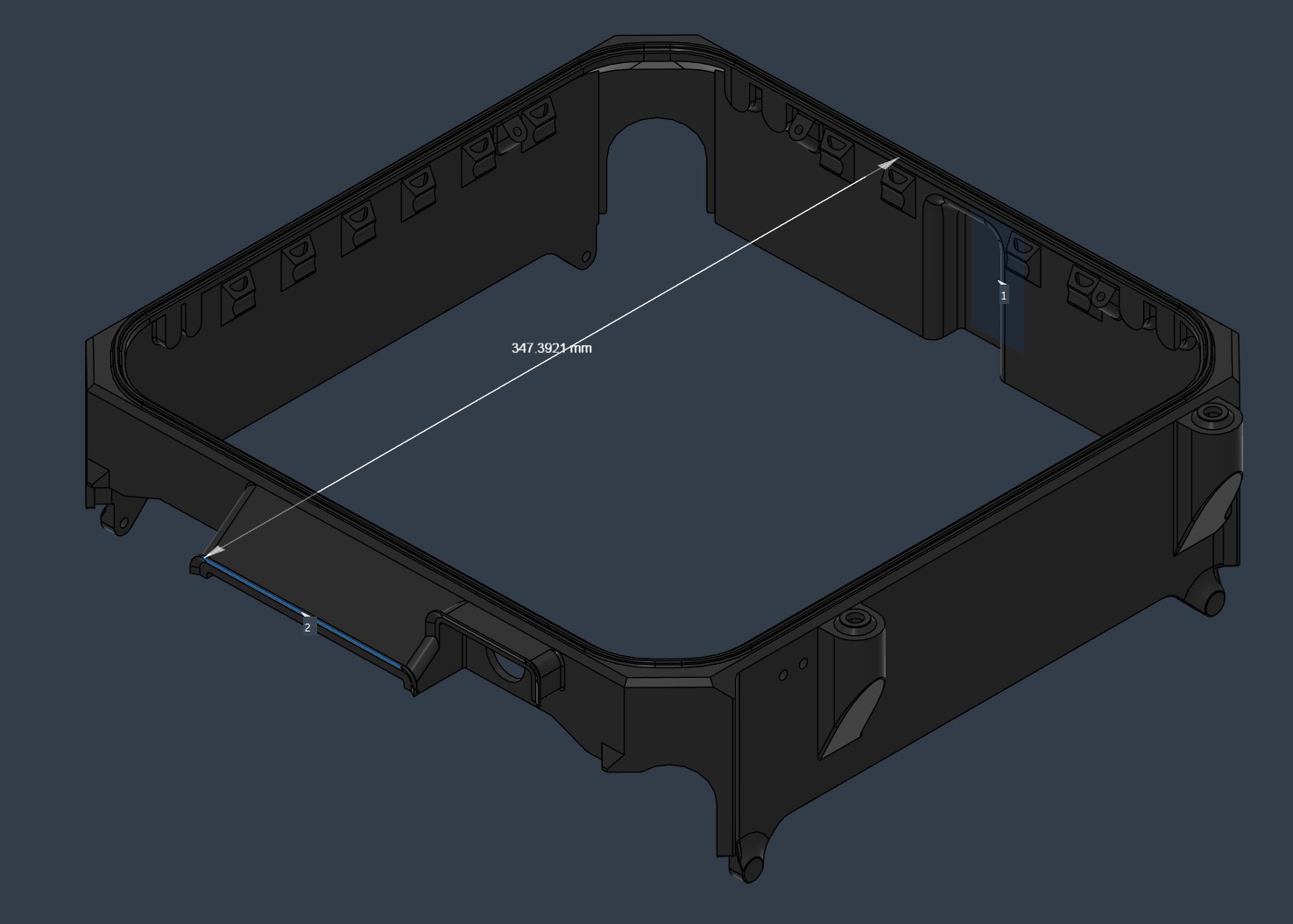
3D Printing Size Optimization (Version 2)
The enclosure total length was reduced from 34.7 cm to 31.4 cm by shortening the battery rain shield and front cable outlet, enabling the enclosure to fit on a wider range of consumer 3D printers.
| Version 1 (34.7 cm) | Version 2 (31.4 cm) |
|---|---|
 | 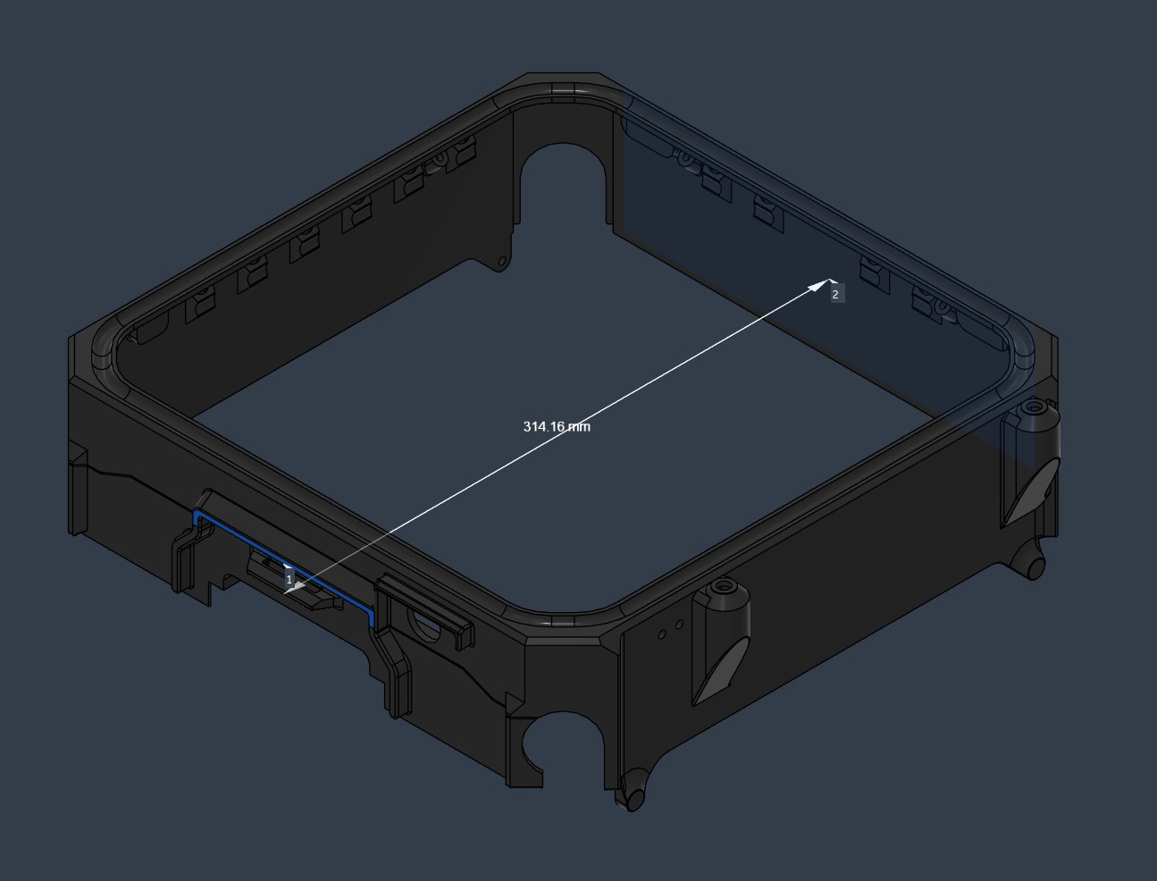 |
Weight Reduction Study
A weight reduction study was conducted by reducing the material thickness of aluminum airframe plates and evaluating the structural impact through FEA simulation and physical flight testing.
Proposed reductions:
| Part | Original | Proposed |
|---|---|---|
| 1101-UpperPlate | 2 mm | 1 mm |
| 1102-MidPlate | 2 mm | 1 mm |
| 1103-LowerPlate | 4 mm | 2 mm |
| 1211-CW_Long | 2 mm | 1 mm |
| 1212/1213-Square_Short | 2 mm | 1 mm |
| 1221/1222-Wall | 2 mm | 1 mm |
FEA results: The lower airframe parts (1221/1222-Wall and 1103-LowerPlate) exhibited significant deformation under a 300 N lateral static force when thinned. The upper airframe parts remained rigid.

FEA displacement under a 300 N lateral static force at the lower frame (unit: mm).
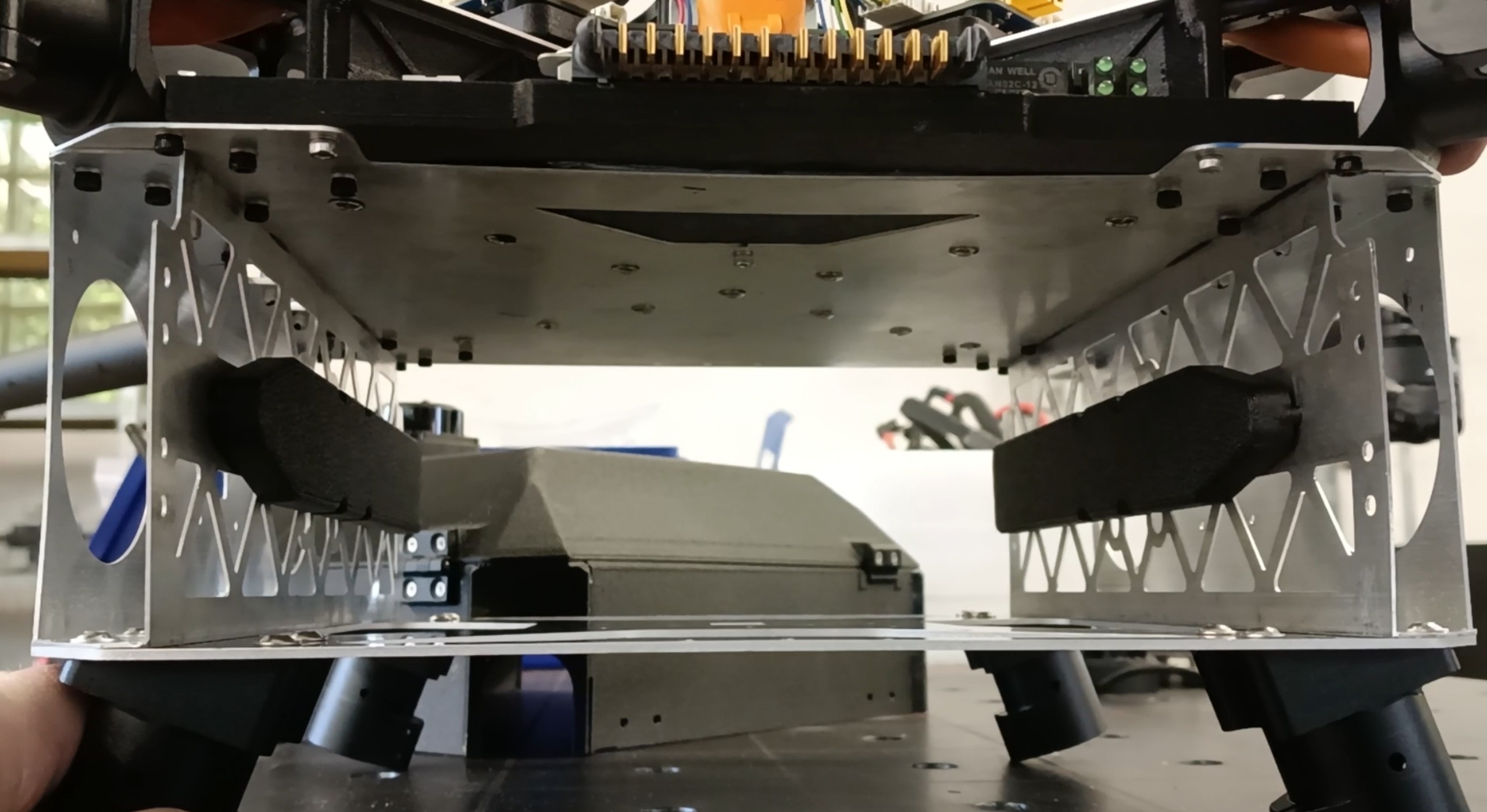
Flight testing results:
-
Without payload: Flight behavior appeared normal on visual inspection, but log analysis showed increased lateral vibrations from wall movement.
Lateral deformation of the lower frame walls visible during physical inspection.
-
With maximum payload (~7 kg): The flight had to be aborted due to strong oscillations. The thinned lower frame was no longer rigid enough under payload weight, causing the flight controller to continuously counteract frame induced instability.

Final decision: Thickness reduced for the upper airframe parts. Lower airframe and battery bay parts remain at original thickness.
| Part | Final Thickness |
|---|---|
| 1101-UpperPlate | 1 mm (reduced) |
| 1102-MidPlate | 1 mm (reduced) |
| 1211-CW_Long | 1 mm (reduced) |
| 1212/1213-Square_Short | 1 mm (reduced) |
| 1103-LowerPlate | 4 mm (unchanged) |
| 1221/1222-Wall | 2 mm (unchanged) |
Final configuration: upper airframe thinned, lower frame and battery bay at original thickness.
Transport Case
The transport solution for the Dev-Kit is a used Pelican 1640 rolling case with custom laser cut foam inserts, selected after a custom hard case was found to be incompatible with the airframe form factor. A 3D printed camera cap protects the gimbal camera during transport.
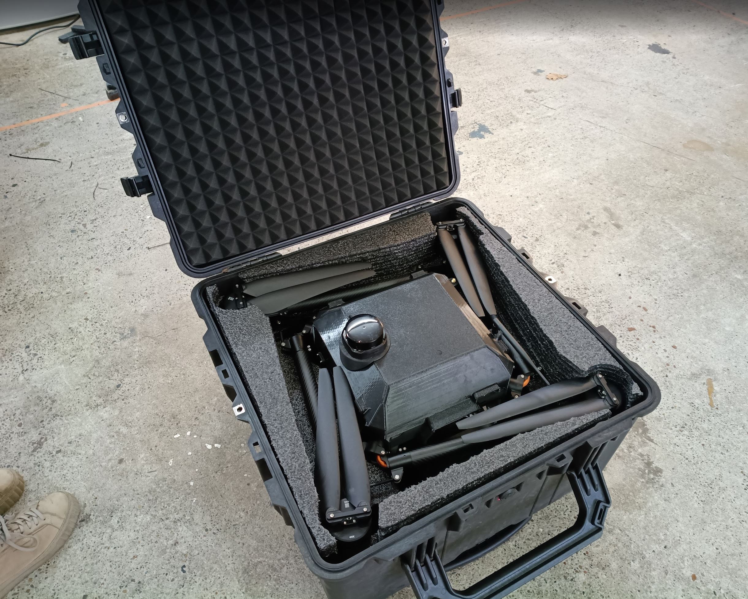
Quiver loaded in the Pelican 1640 transport case.
Detachable Landing Gear
25 mm diameter landing gear was tested first and subsequently upgraded to a custom 30 mm diameter variant manufactured by RJX Hobby. A 120-unit batch order was placed in January 2026.
Altitude Sensor Mount Redesign
The altitude sensor mount was fully redesigned to accommodate the two new sensor modules (Ainstein US-D1 radar altimeter and Benewake TF03-180 LiDAR altimeter) and to simplify the wiring process of the previous design.
The new mount uses an X-pattern upper structure for weight reduction and improved 3D printing sliceability. The pattern also provides natural cable organization for altitude sensor wiring. Screw insert bases for the forward facing radar use large chamfers to enable supportless 3D printing.
The SIYI gimbal camera was repositioned to the right side of the aircraft. The installation method is unchanged from the PT3 design.
| Design | Installed |
|---|---|
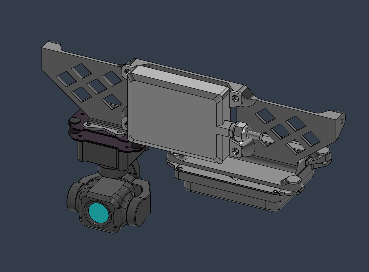 | 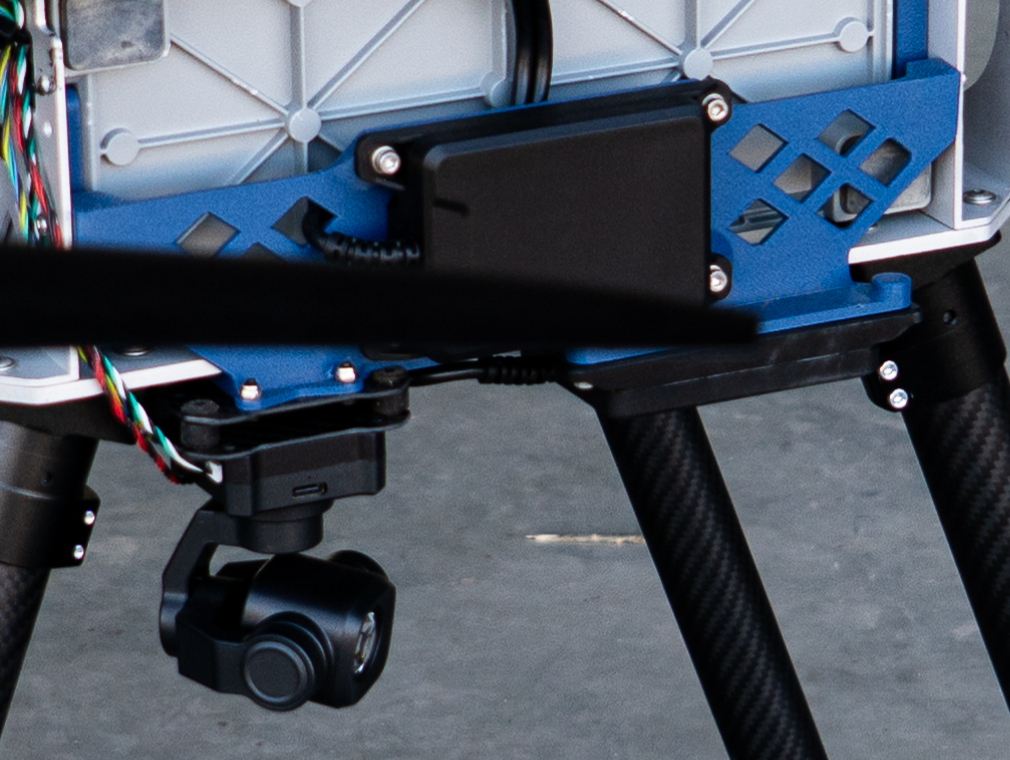 |
Electronics Integration
PCB Vibration Isolation Mount
The Main PCB is secured to a custom 3D printed PETG-CF adapter plate, which mounts to the aluminum upper plate through five rubber vibration dampeners. The mount floats entirely on the dampeners and must not make contact with the aluminum frame at any point — any direct contact defeats the isolation. This decouples high frequency motor and propulsion vibrations from the PCB assembly and flight controller sensors.
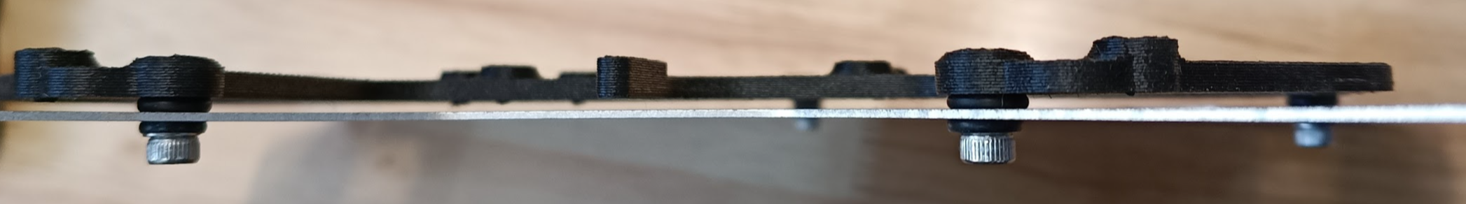
One design constraint to note: the through-hole pins of the DC-DC converters on the underside of the Main PCB extend far enough to puncture the adapter plate or short against the frame if not trimmed before installation.
Battery PCB Updates
The Battery PCB was updated with the following changes:
MOSFET upgrades (higher power ratings):
- Q1: Pre-charge MOSFET
- Q8: 12V control MOSFET
- Q9: Bypass MOSFET
Protection and routing:
- Protection diodes D10 and D11 added
- Main power output cables replaced with copper bus bars for improved current capacity and mechanical reliability
- Second SSR signal added on J3 (connector 1778735) for redundancy
- Silkscreen updated to reflect correct pushbutton wiring
Main PCB Updates
The Main PCB is the central hub routing power and signals between the flight controller and all major subsystems, including payload ports, sensors, the Raspberry Pi, telemetry units, and Ethernet infrastructure. The Dev-Kit revision built on the PT3 first revision with the following improvements:
| Front | Back |
|---|---|
 | 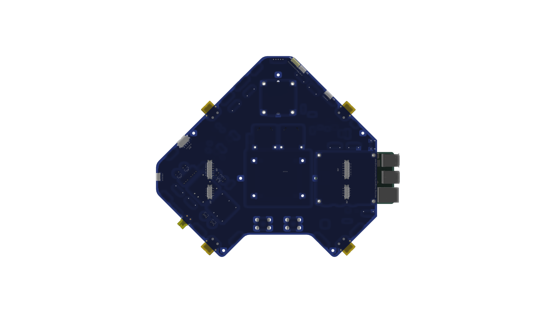 |
Connector updates:
- Switched to JST-GH connectors for HM30 Air Unit (J15, J17), auxiliary CAN connections (J18, J20, J22), and GNSS (J5, J7)
- Dedicated 360° LiDAR connector added (U5)
Power system:
- New "Power Supply" schematic sheet added for 5V and 12V supplies
- Capacitors C2, C9, C13, C16 added to PS1; C8, C10, C14, C17 added to PS2
- Backup 5V supply added (U4) for flight controller redundancy
- New "Power Control" schematic sheet added for payload/HV switching
- Updated control scheme using a CPC1019N SSR to drive a high power MOSFET
- Fuses, LED indicators, and protection circuitry added (see schematic for full detail)
Redundancy:
- Redundant SSR control trace added: J46 Pin 5 (IO_CH5_Backup) provides a backup signal path to prevent signal loss
Mechanical integration:
- SMD-soldered threaded standoffs added for GNSS (U3, U6–U8), Raspberry Pi (U9–U12), and Ethernet switches (U13–U16)
Layer strategy: The 6-layer PCB layout uses dedicated layers for power routing, CAN bus, and Ethernet signals.
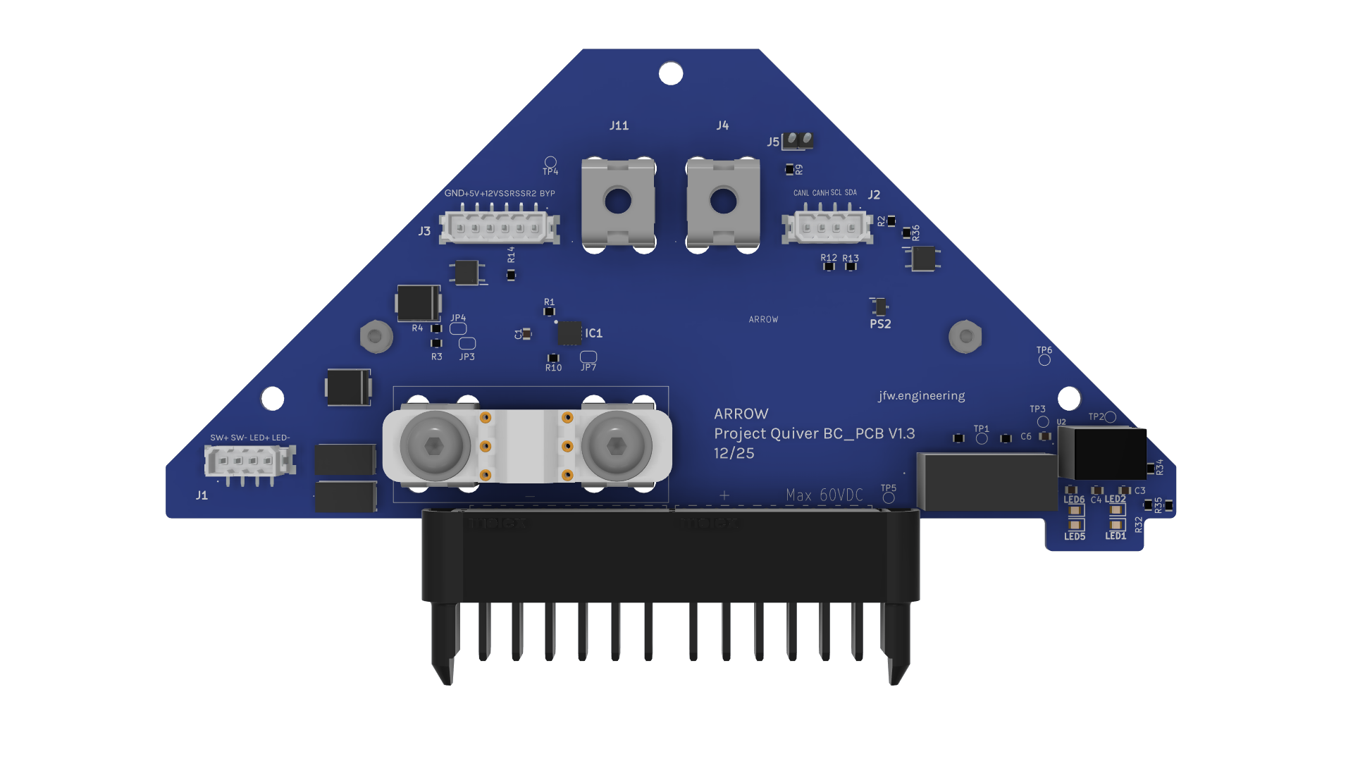
Attachment Interface PCB
The Attachment Interface PCB provides the electrical interface between the Main PCB and each of the three payload ports (C1, C2, C3). It routes regulated 12V power, CAN bus signals, and Ethernet (on C1 and C2) from the Main PCB to the payload through pogo-pin contacts at the quick-release attachment point. The board is designed for hot swap operation, allowing payloads to be connected and disconnected without disturbing the main electronics stack.
The Dev-Kit introduced a revised version of the Attachment Interface PCB (V1.4) focused on manufacturability and mechanical interfacing improvements. All original functional characteristics are retained.
The primary change replaces the J2 and J3 connectors with individual spring loaded pin headers (U1–U20), with enlarged solder pads on the corresponding contact side to improve the interface with the pogo pins at the quick-release attachment point. Solder pads across the board were extended to improve assembly robustness, PCB routing was updated to use rounded trace edges, and an orientation notch was added to the silkscreen to reduce assembly ambiguity.
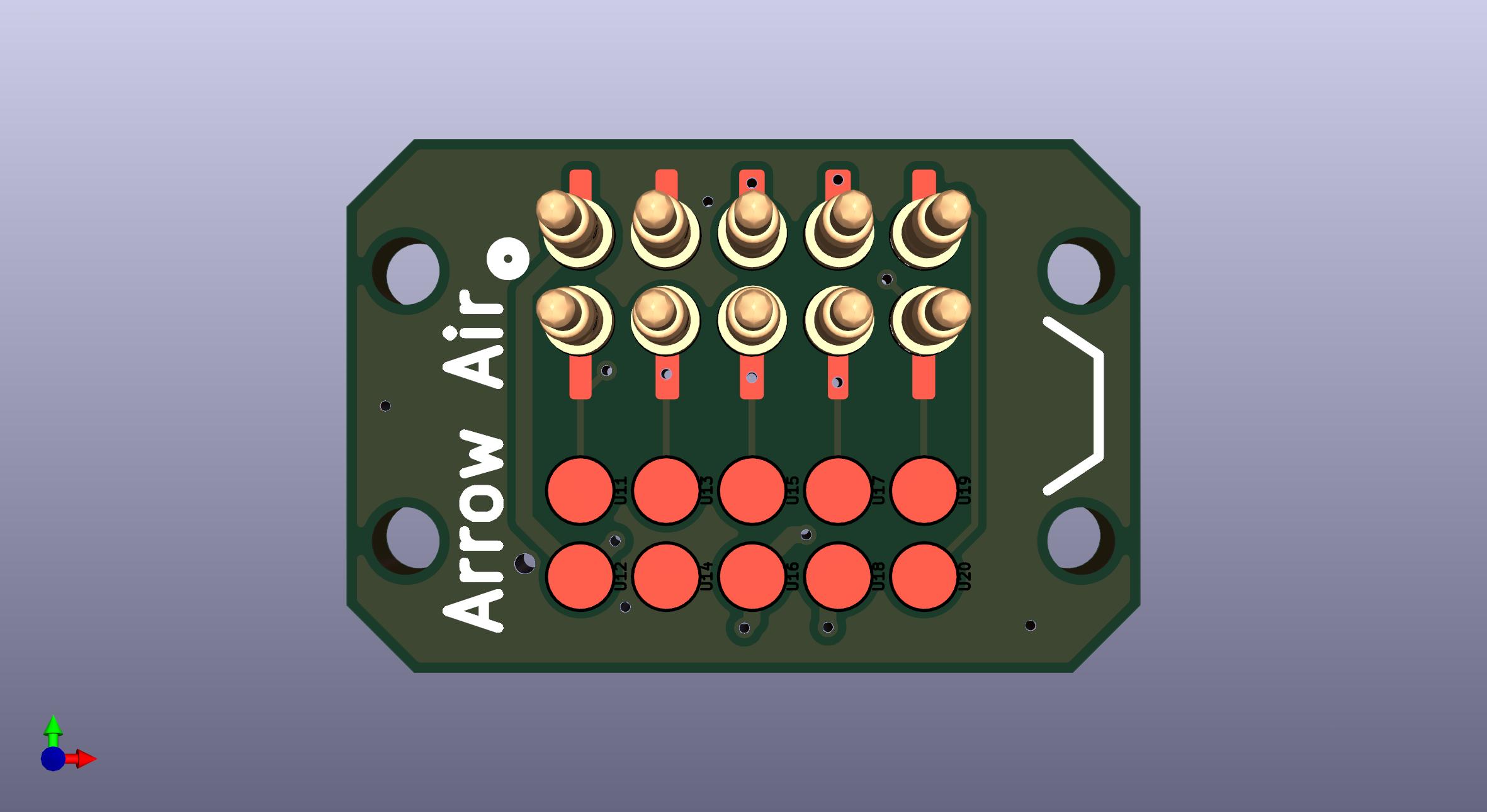 | 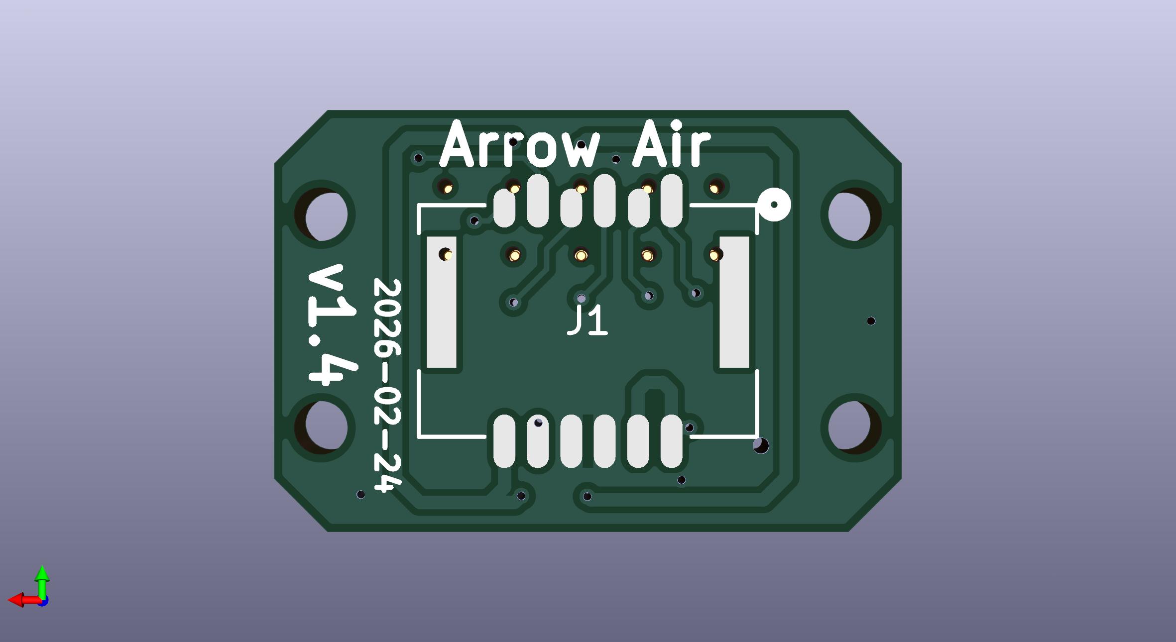 | 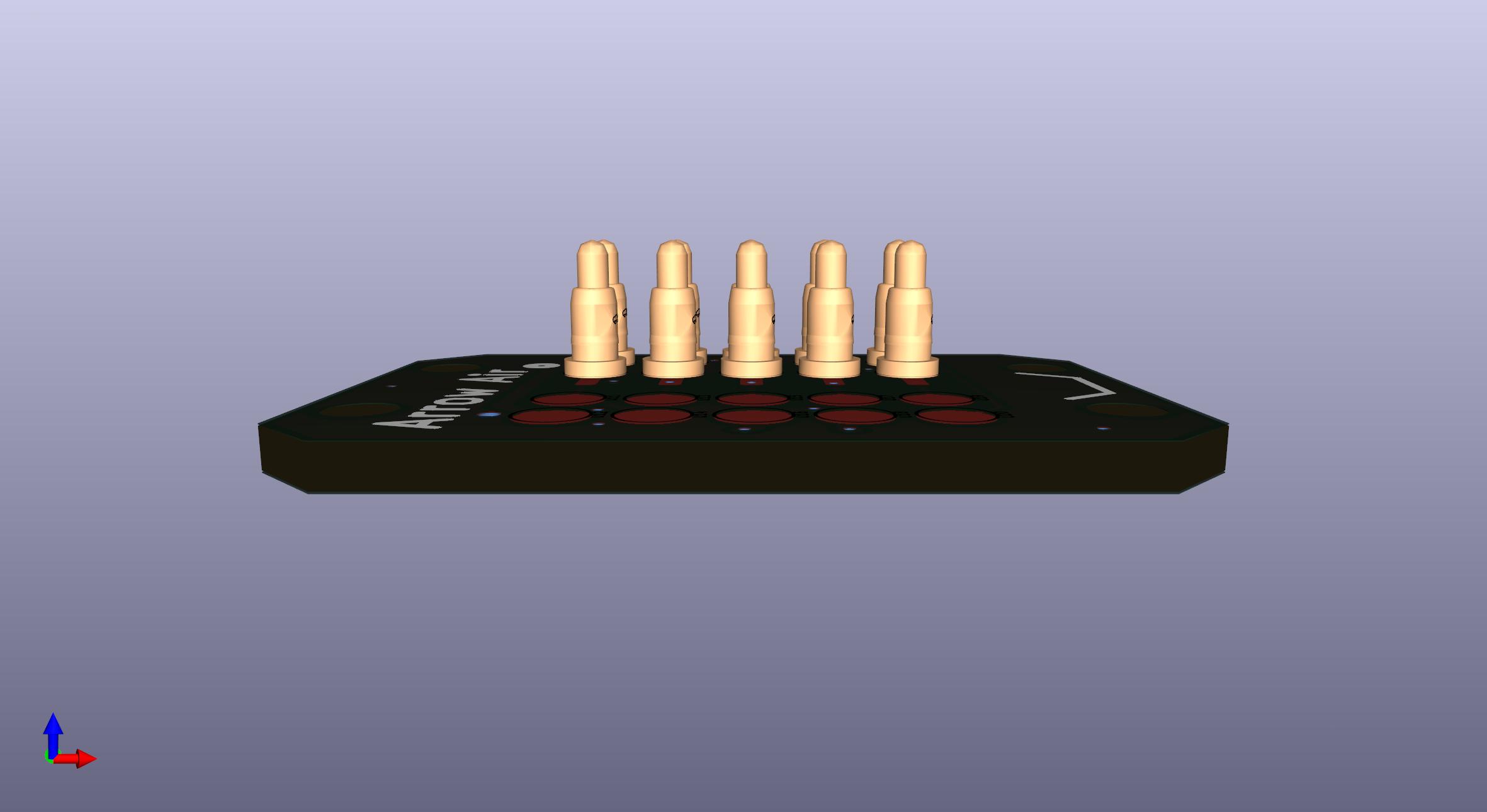 |
For detailed design documentation, refer to the Attachment Interface PCB V1.4 Information Note.
Raspberry Pi Integration
The Raspberry Pi 4/5 companion computer is mounted directly on the Main PCB via the SMD threaded standoffs. It serves as the intelligent bridge between the flight controller, payload ports, and Quiver Hub.
During Dev-Kit development, the following integrations were validated:
- Battery data visualization via MAVSDK web interface
- REST File Get Client for bidirectional communication with Quiver Hub
- RPLidar C1 terrain mapping payload pipeline (end to end from sensor to browser visualization)
- Obstacle avoidance parameter management via Lua scripting on ArduPilot
The 5V power supply on the Main PCB was upgraded to support the power budget of the Raspberry Pi and a 4G/LTE cellular modem simultaneously.
Ethernet Integration
Two GigaBlox Nano 1-inch Gigabit Ethernet switches are installed on the Main PCB, providing Ethernet connectivity to the three payload ports (C1, C2, C3) and to the flight controller via the CubeNode ETH DroneCAN to Ethernet adapter.
Network topology (drone subnet: 192.168.144.x):
All onboard devices share a flat 192.168.144.0/24 network. Several addresses are hardcoded by SIYI hardware firmware and cannot be reconfigured — all other device assignments must avoid these reserved addresses.
Quiver device assignments:
| Device | IP Address |
|---|---|
| CubeNode ETH adapter | 192.168.144.10 |
| Raspberry Pi (companion computer) | 192.168.144.50 |
| Flight Controller | 192.168.144.51 |
| Payload bottom port (C1) | 192.168.144.100 |
| Payload side port 1 (C2) | 192.168.144.101 (default, see note) |
| Payload side port 2 (C3) | 192.168.144.102 (default, see note) |
| Ground station laptops / dev machines | 192.168.144.200–254 |
SIYI reserved addresses (do not use):
| IP Address | Device |
|---|---|
| 192.168.144.11 | SIYI air unit |
| 192.168.144.12 | SIYI ground unit |
| 192.168.144.20 | Android ground station (SIYI) |
| 192.168.144.25 | SIYI A8 Mini camera |
| 192.168.144.60 | SIYI cameras (reserved, unused) |
Payload and attachment developers should assign static IPs in the 192.168.144.100–199 range. Earlier SDK documentation assigned C1=.11, C2=.12, C3=.13 — those addresses conflict with SIYI hardware and should not be used.
[!NOTE] On side port IPs: The bottom port assignment (.100) is fixed because that port is always the bottom. Side port assignments (.101/.102) are defaults based on physical port position. Attachments designed to work on either side port should treat their IP as a configurable parameter rather than a hardcoded value, so operators can reassign it to match whichever port the attachment is actually mounted on.
The switches are secured to the Main PCB using M2x6 screws. Dev-Kit PCBs have spacers already soldered; older PCBs require a separate spacer and nut.
Remote ID Integration
A DroneBeacon db201 (Bluemark) is mounted inside the main enclosure on the floating module mounting plate alongside the Ethernet adapter. The module runs ArduRemoteID firmware on an ESP32 processor and broadcasts operator and drone identity over WiFi and Bluetooth Low Energy simultaneously. Integration was validated on April 10, 2026 running ArduCopter V4.7.0-dev on the Pix32 v6, connected via DroneCAN.
Remote ID requires the Quiver custom ArduPilot firmware build (PR #183, feature/firmware-docs-v2), compiled with AP_OPENDRONEID_ENABLED=1. Stock ArduPilot firmware does not include this capability. Operator and drone IDs are configured per operator via Mission Planner or automated through a Python script running as a systemd service on the Raspberry Pi.
GCS GPS requirement:
The flight controller requires a GCS GPS fix to pass the "operator location must be set" pre-arm check. Laptops without built in GPS can satisfy this using an Android phone running GPS NMEA Tether, which streams NMEA data to Mission Planner over Bluetooth SPP. During indoor validation, 25–28 satellites were received via this method. GCS GPS HDOP is elevated indoors, which produces a yellow status indicator and is expected to resolve with an outdoor fix.
Bluetooth scan validation:
A BLE scan using a Remote ID scanner app (OpenDroneID / DroneScanner) confirmed the following fields broadcast correctly:
| Field | Status | Notes |
|---|---|---|
| UAS ID (Serial Number) | Visible | |
| Operator ID | Visible | |
| UA Type | Visible | Helicopter/Multirotor |
| Self ID / Description | Visible | Free-text field |
| Drone location (lat/lon/alt) | Visible | From FC GPS |
| Operator location | Visible | From GCS GPS |
| Manufacturer / Model | "Unknown" | See note |
The "Unknown" manufacturer field is not populated by ArduRemoteID firmware and cannot be configured. This field is optional under ASTM F3411 and the EU Remote ID standard and has no compliance impact.
Remote ID integration is validated. Per unit configuration is required before shipment to each operator: UAS_ID must be set to the registered serial number and Operator ID to the operator's CAA registration. Both FAA Part 107 compliance (US) and EASA Open Category operations (EU) require this configuration to be completed.
Software Upgrades
Quiver Hub
Quiver Hub is a web application that serves as the ground control and data operations center for the Quiver ecosystem. It is built around a three tier architecture: a browser based frontend, a Node.js server handling API, real time streaming, persistence, and job orchestration, and an onboard companion computer fleet running relay and job execution services. Sensor data from drones flows up to Hub for display and storage through REST ingestion endpoints. Commands from operators flow down through a job queue to the companion computer for local execution. Real time data distribution to the browser uses WebSocket streaming. Browser to server operations use typed RPC.
Implemented:
- LiDAR Visualization: Real time 2D and 3D display of RPLidar point cloud data as it arrives from the drone. Includes a demo mode for offline testing without a live sensor.
- Flight Telemetry: Live dashboard showing attitude, position, GPS state, and battery status from both the flight controller and the smart battery.
- Camera and Gimbal Control: Live video stream from the SIYI A8 camera to the Hub interface, validated in March 2026, with controls that relay gimbal commands through the companion computer.
- Flight Analytics: Post-flight log analysis using ArduPilot DataFlash logs parsed client-side in the browser, with charts covering attitude, navigation, power, vibration, radio link, and EKF state. Includes a flight mode timeline, side by side log comparison, and summary export.
- Drone Configuration: Fleet management covering drone registration, API key management, connection testing, file upload to the companion computer, and job dispatch.
- Developer extensibility: App Store and App Builder framework for publishing custom data pipeline applications. Supports custom ingestion endpoints, server side Python payload parsing, and UI widgets bound to live data streams. App versioning and rollback are included.
- Flight Log Module (Logs v1): Full FC to companion to Hub log pipeline. Operators can trigger a scan job, browse discovered logs, request downloads from the flight controller, store retrieved logs in Hub, download them through the browser, and forward completed logs into analytics workflows.
- OTA Update Module (OTA v1): Firmware upload with SHA-256 hashing, staged delivery through the companion computer, companion-side integrity verification before flashing, and flash execution on the flight controller. Includes Hub side listing, upload, job request, and failed record cleanup.
- Security baseline: Artefact integrity verification enforced at flash time via SHA-256 hash comparison. Job reliability layer implemented covering retry handling, expiry, timeout reaping, locking, and cleanup for stuck or failed work. Job allow listing and permissions hardening are sequenced as follow-on work alongside the broader SDK integration layer.
- Diagnostics and Remote Logs: Dedicated views for flight controller logs, OTA update status, diagnostics, and remote log access.
Remaining development:
- Job allow-listing and typed job permissions hardening
- Mission Planner UI
- Standalone local deployment and hosted SaaS deployment strategies
- Multi-user and fleet scaling validation
- Database migration tooling and operational backup strategy
Quiver Payload SDK
The Quiver SDK is a Python development toolkit for companion computer and payload integration. A formal architecture specification was drafted in March 2026 and the SDK was published to its own repository in April 2026. The features described below are planned; none of the formal SDK packages are implemented yet. The existing telemetry forwarder and job runner scripts on the Raspberry Pi predate the SDK spec and will eventually be replaced by it.
Planned architecture:
The SDK is designed as two separate packages. quiver-sdk is the core hardware abstraction layer, providing Python interfaces for vehicle control via MAVLink, camera and gimbal operation, and communication with payload devices over Ethernet and CAN. It is designed to run on the onboard Raspberry Pi or any machine on the drone network and does not require internet connectivity. quiver-hub is a separate integration layer that imports quiver-sdk and adds telemetry forwarding to Quiver Hub, a job runner for executing remote commands, and a payload data streamer. Developers building onboard autonomy only need quiver-sdk. Developers building Hub-integrated applications install both.
For the MAVLink layer, pymavlink was selected over MAVSDK on the basis that Quiver runs ArduCopter and pymavlink is maintained by the same team, exposing all ArduPilot-specific messages. ROS2 integration was considered but placed out of scope for the v1 release.
Development roadmap:
Nine milestones cover the full SDK delivery:
- M1–M2: Vehicle control and camera interfaces validated on real hardware
- M3–M5: Payload attachment API covering raw device communication, typed streams, and the payload contract specification
- M6–M7:
quiver-hublayer replacing the existing telemetry forwarder and job runner scripts - M8: Payload data streaming integrated with Hub App Builder
- M9: PyPI publication, systemd service templates, and developer documentation
Existing proof of concept:
Prior to the formal SDK specification, a terrain mapping pipeline was implemented and validated:
RPLidar C1 → Raspberry Pi (TCP, 10 Hz) → HTTP POST → Quiver Hub → Browser (WebSocket)
- Scan rate: 8–12 Hz (target 10 Hz)
- Points per scan: 250–500 (typical ~350)
- End to end latency: ~100–150 ms
This pipeline informed the SDK architecture and serves as the reference implementation for the payload streaming layer.
GitHub: https://github.com/Arrow-air/quiver-sdk
Obstacle Avoidance Selection, Tuning, and SITL Simulation
Sensor configuration:
| Sensor | Coverage | Range | Role |
|---|---|---|---|
| RPLidar S2L | 360° horizontal | ~18 m | Primary proximity input to BendyRuler |
| NanoRadar MR82 | Forward sector | ~30 m | Supplemental forward detection in degraded conditions |
| Barometer + Rangefinder | Vertical | — | Altitude estimation and terrain clearance |
ArduPilot custom firmware:
The RPLidar S2L is not natively supported in upstream ArduPilot. The Dev-Kit operates on a custom ArduPilot build incorporating an in house sensor driver extension. The patch is limited to driver support and proximity interface integration, with no modifications to core navigation or avoidance algorithms. An upstream pull request has been submitted: https://github.com/ArduPilot/ardupilot/pull/31663
Obstacle avoidance algorithm: BendyRuler (OA_TYPE = 1)
Proximity database:
| Parameter | Value | Description |
|---|---|---|
OA_DB_SIZE | 100 | Max stored obstacle points |
OA_DB_QUEUE_SIZE | 80 | Queue depth for incoming data |
OA_DB_EXPIRE | 3 s | Obstacle point expiry time |
OA_DB_OUTPUT | 3 | Output mode |
OA_DB_BEAM_WIDTH | 10° | Angular obstacle representation width |
OA_DB_RADIUS_MIN | 0.2 m | Minimum obstacle radius |
OA_DB_DIST_MAX | 10 m | Maximum distance for obstacle storage |
BendyRuler motion constraints:
| Parameter | Value | Description |
|---|---|---|
OA_BR_TYPE | 1 | BendyRuler enabled |
OA_BR_LOOKAHEAD | 12 m | Forward projection distance |
OA_BR_CONT_RATIO | 1.2 | Continuity weighting |
OA_BR_CONT_ANGLE | 60° | Max directional change |
OA_MARGIN_MAX | 4 m | Minimum clearance from obstacles |
OA_OPTIONS | 1 | Basic avoidance features enabled |
The 4 m obstacle margin is intentionally set low to allow maneuvering within tree dense environments where larger margins prevent feasible path planning. Dynamic margin scaling as a function of ground speed is under investigation.
SITL simulation:
A Software in the Loop simulation environment was established using the same ArduPilot branch and parameter set as the flight hardware. An SF45 LiDAR model substitutes for the RPLidar S2L. The environment is launched with:
../Tools/autotest/sim_vehicle.py --map --console \
  -A "--serial5=sim:sf45b --serial6=sim:obstacle"
SITL results are used to identify safe parameter ranges and inform flight test planning. They are not a substitute for real hardware validation.
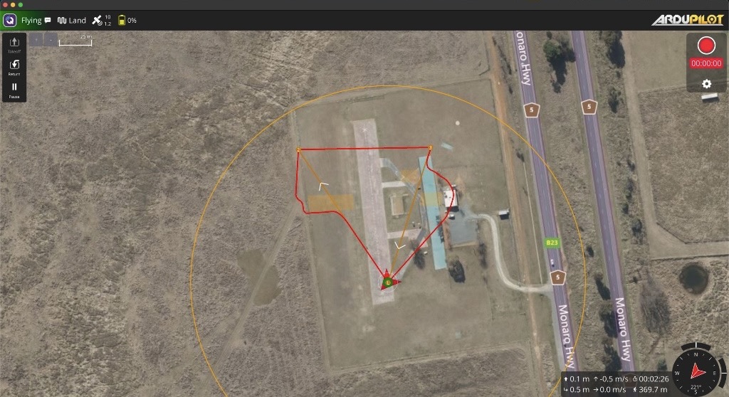 | 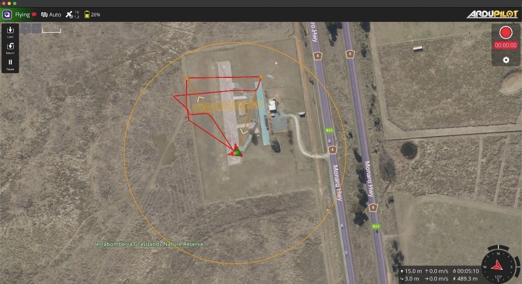 |
QGroundControl views of the SITL obstacle avoidance simulation.
Flight testing roadmap:
| Phase | Environment | Focus |
|---|---|---|
| 1: Sensor Checks | Open field (Texas) | Sensor alignment, 360° yaw test, person with board obstacle |
| 2: Manual Control | Open field | Circling, stick disturbance, narrow gate, payload impact |
| 3: AUTO Missions | Open field | Waypoint missions with single and dual obstacles |
| 4: Dense Environments | Germany (trees) | Parameter validation with Texas baseline settings |
Pass criteria:
- Zero obstacle contact
- At least 95% AUTO mission success rate
- Separation of at least
OA_MARGIN_MAX− 1 m at all times
Known issue: As of March 2026, the S2L LiDAR exhibits intermittent dropouts during flight, despite reliable ground performance. Suspected cause is vibration resonance or electrical load interaction. Under active investigation.
Weight & Payload Summary
Configuration Summary
| Configuration | Battery | Battery mass | Empty weight | AUW | Payload capacity |
|---|---|---|---|---|---|
| Standard | 20Ah LiPo (14S) | 7.90 kg | 9.65 kg | 17.55 kg | 7.45 kg |
| Long endurance | 30Ah LiPo (14S) | 11.40 kg | 9.65 kg | 21.40 kg | 3.95 kg |
| MTOW limit | — | — | — | 25.00 kg | — |
Payload capacity = MTOW − empty weight − battery mass. MTOW is 25 kg per the intended regulatory category.
Subsystem Breakdown
Empty weight covers the full Dev-Kit build as shipped, including the NanoRadar MR82 forward-facing radar (92 g) and attachment interface cables (~100 g). Battery is excluded.
| Subsystem | Items | Mass |
|---|---|---|
| Airframe Structure | Upper/mid plates, lower plate, motor arms, CF tubes, landing gear | TBD |
| Propulsion | 4× XRotor X6 PLUS (motor + ESC + props, 790 g each) | 3.16 kg |
| Avionics & Sensors | Pix32 v6 (36 g), RPLidar S2L (190 g), NanoRadar MR82 (92 g), Ainstein US-D1 (110 g), Benewake TF03-180 (89 g), Holybro F9P (60 g), Mateksys M9N (16 g), SIYI A8 mini (95 g), SIYI HM30 air unit (74 g), DroneBeacon db201 (4 g), sensor mount (TBD) | TBD (≥ 766 g) |
| Custom PCBs | Main PCB, Battery PCB, FC PCB, 3× Attachment Interface PCB | TBD |
| Companion Computer | Raspberry Pi 5 (47 g), 2× GigaBlox Nano (18 g each), CubeNode ETH (7 g) | 90 g |
| Enclosure & Mounts | Enclosure body, cockpit lid, PCB vibration mount, module plate | TBD |
| Harness | Wiring, connectors, attachment interface cables | TBD |
| Hardware & Fasteners | Screws, standoffs, grommets, misc | TBD |
| Total empty weight | 9.65 kg |
Performance Metrics & Endurance Testing
The Dev-Kit performance evaluation follows a standardized methodology for comparing prototypes across control behavior, stability, efficiency, and navigation accuracy. Metrics are extracted from ArduPilot flight logs using Mission Planner, MAVExplorer, and custom scripts. Tests cover rate tracking error, vibration analysis, power efficiency, climb performance, yaw authority, waypoint tracking, and glide capability. Results are collected under consistent environmental and configuration conditions to ensure fair comparisons.
PENDING TEST RESULTS — Endurance and performance metrics flight testing is planned for May 2026 / ongoing.
Beta Testing
External field testing of the first Dev-Kit units is planned following endurance flight validation, completion of the documentation suite, and GPS/4G RF interference investigation. Target beta operators have been identified.
PENDING
Conclusions & Future Recommendations
The Dev-Kit phase achieved its primary objective of converting the PT3 prototype into a shippable developer platform. The structural, electronics, and software work are well integrated, and the weatherproofing validation, vibration isolation, and obstacle avoidance integration represent meaningful advances over PT3.
The most important lesson from this phase concerns structural weight reduction under payload. The decision to keep lower airframe plates at original thickness came from a flight test result that FEA did not fully predict. The thinned lower frame was airworthy without a payload but unsafe with one. This validates the need to test structural changes at the weight conditions the aircraft will actually operate under, not just at empty weight.
On the software side, the terrain mapping pipeline served as a proof of concept that informed the SDK architecture. Quiver Hub's App Store and App Builder framework provides an extensibility path for payload developers, though the developer documentation required to make that accessible is still in progress.
The obstacle avoidance system is the most analytically complete subsystem in the Dev-Kit: SITL validated parameters, a structured four phase test roadmap, clear pass criteria, and a documented known issue. The approach of running SITL analysis before field testing proved useful and should be applied to future subsystem work.
Remote ID integration was validated in April 2026 via DroneCAN, clearing the last hardware blocker ahead of external shipments. Per operator configuration of the UAS ID and operator credentials is required before each unit ships, which is an operational step rather than an open engineering item.
Open items heading into field deployment:
- Endurance and performance metrics flight validation (planned May 2026)
- Obstacle avoidance field testing across four phases
- LiDAR dropout root cause analysis (suspected vibration or electrical load interaction)
- GPS/4G RF interference investigation and resolution
- Actuated payload latch mechanism (bounty in progress)
- Multispectral camera payload (bounty in progress)
- EASA C3 certification pathway (deferred, estimated €17k–20k)
Appendices
Dev-Kit Information Notes
- Main PCB Update
- Battery PCB Update
- PCB Vibration Mount
- Comprehensive Main Enclosure Modification
- Structure Weight Reduction
- Improvement of Dust and Water Resistance
- Sensor Mount Re-modeling
- Obstacle Avoidance
- SITL Evaluation
- Ethernet Setup Guide
- Quiver Hub V1 (M1–M3)
- Quiver SDK
- Quiver SDK Test