Project Quiver Dev-Kit Manufacturing Guide
PCB Assembly Guides
Main PCB
This chapter will help with the project Quiver Main PCB assembly process.
[!Note] This is not a final version of this document. The given instructions will give a general guide on the assembly process. Assembly should only be carried out by an experienced worker with experience in SMD soldering and the appropriate equipment. If you need this PCB fully assembled please contact the project Quiver team.
This PCB can be ordered fully assembled from the respective PCB manufacturer (e.g. JLCPCB). There are several parts that are normally not in stock at the PCB manufacturer and need to be sourced from one of the large electronic component distributors by the PCB manufacturer. This means that the production time for a finished PCB is around 3 weeks.
The manual soldering of the circuit board can be done with the help of this interactive BOM which is stored in the respective github folder of this PCB (it is not recommended):
Quiver_Dev-Kit_Main_PCB_ibom.html
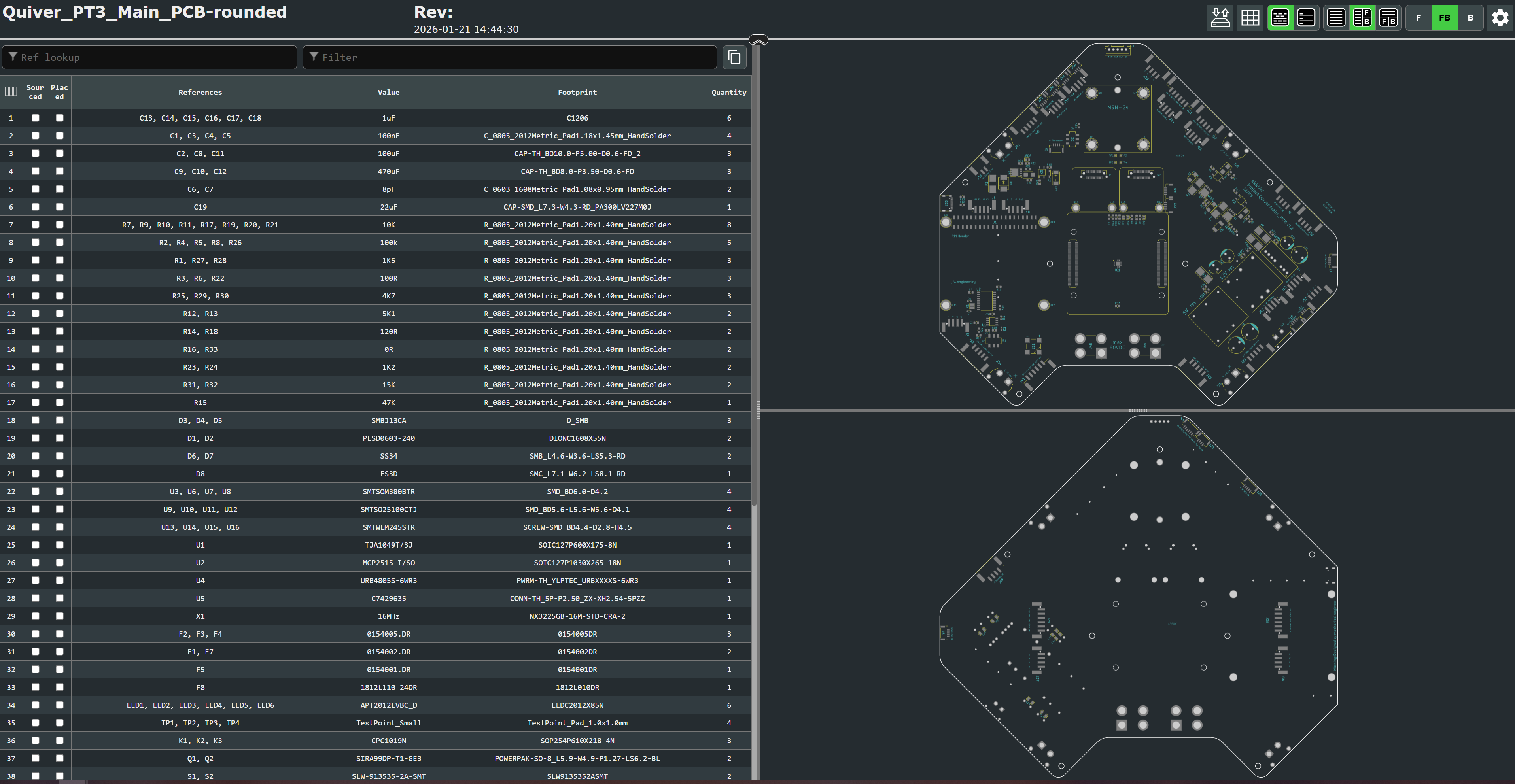
This is an HTML file that opens in the browser. On the left side is the parts list and on the right side are the views for the front and back of the circuit board. It will help to put the components in the right place.
It is essential to use a pcb stencil to place the solder paste in the right places. A reflow oven or a hot air blower (temperature and airflow controllable) should be used for the soldering process.
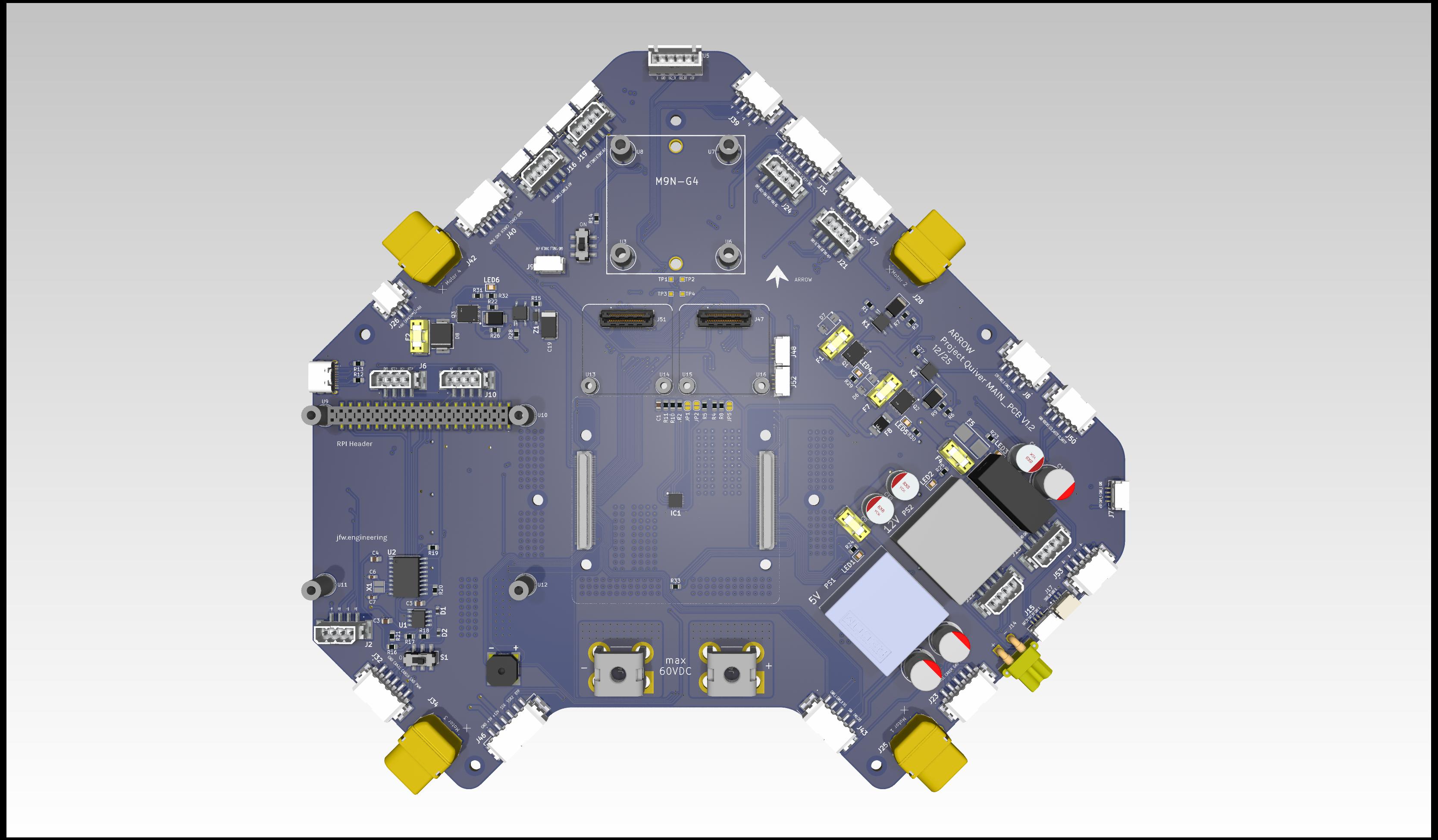
View on the top side of this PCB:
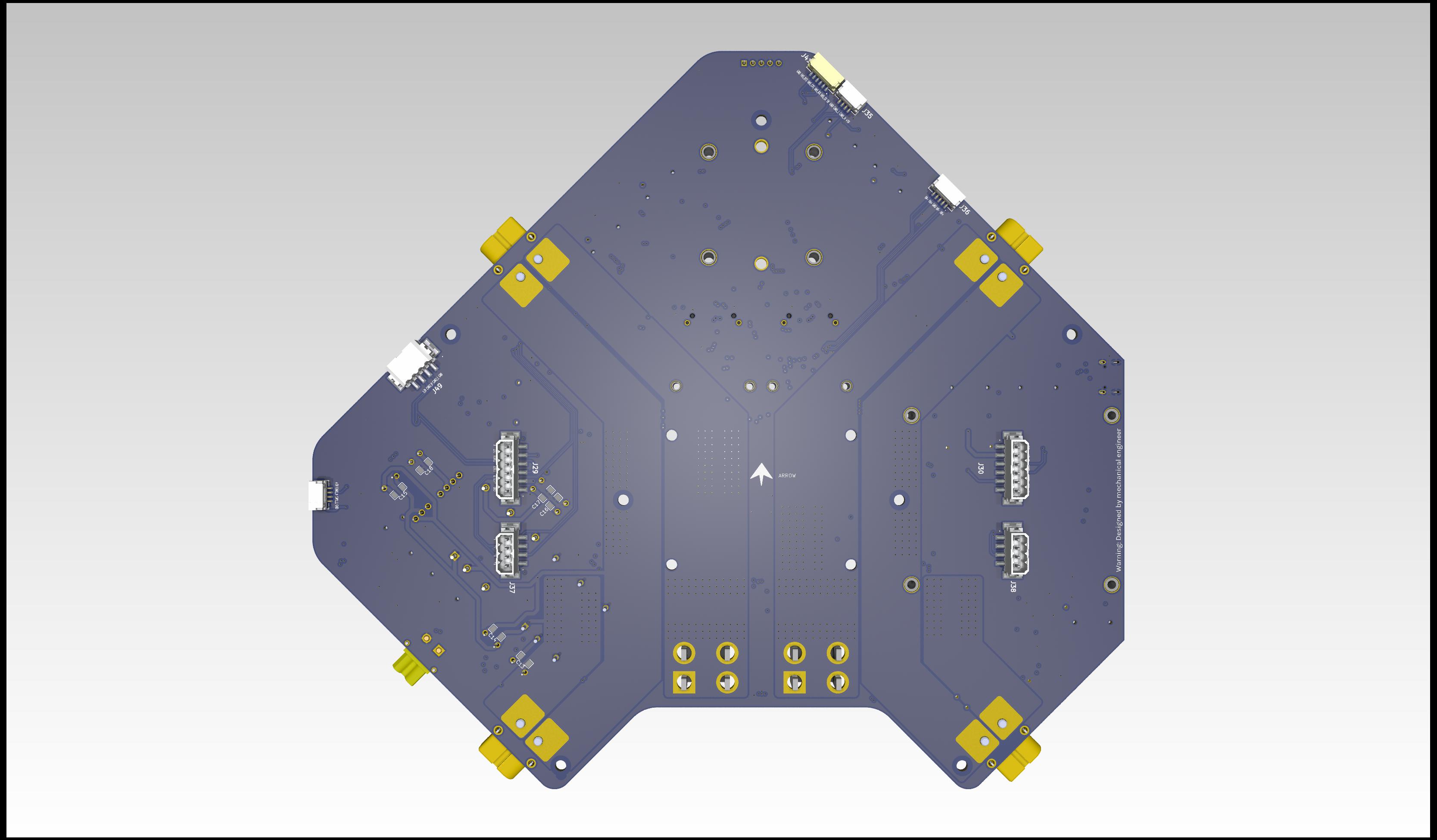
View on the bottom side of this PCB:
Additional Steps
The main pcb has designated mounting positions for additional devices apart from the flight controller:
- Raspberry Pi
- GNSS
- 2X 4 port ethernet switch
These additional devices are not necessary to ensure the basic function of the board.
Battery Control PCB
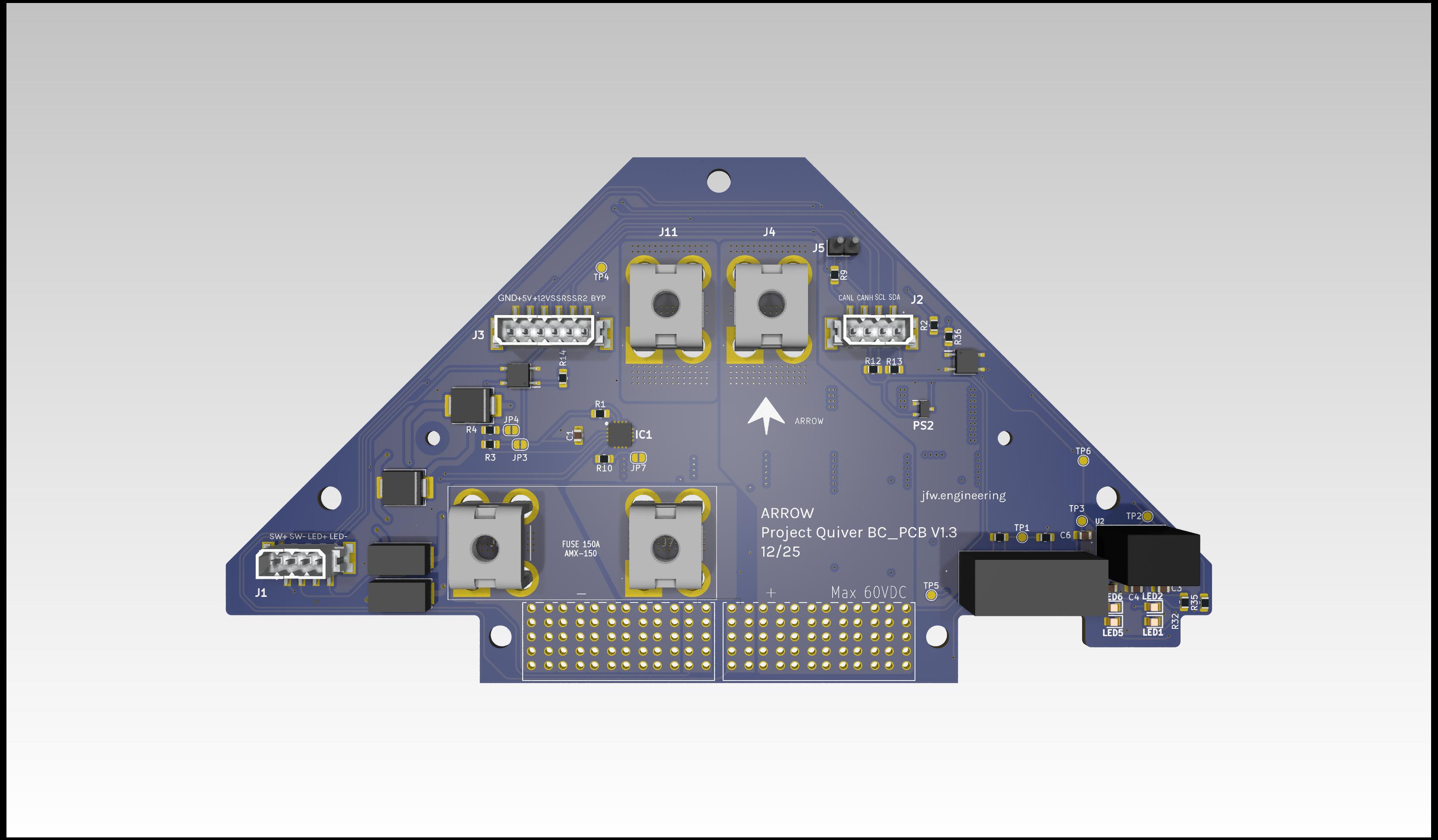
This chapter will help with the project Quiver BC PCB (Battery connector PCB) assembly process.
[!Note] This is not a final version of this document. The given instructions will give a general guide on the assembly process. Assembly should only be carried out by an experienced worker with experience in SMD soldering and the appropriate equipment. If you need this PCB fully assembled please contact the project Quiver team.
This PCB can be ordered (almost) fully assembled from the respective PCB manufacturer (e.g. JLCPCB). There are several parts that are normally not in stock at the PCB manufacturer and need to be sourced from one of the large electronic component distributors by the PCB manufacturer. This means that the production time for a finished PCB is around 3 weeks.
The large molex battery connectors (J9, J10) still need manual assembly at the moment. A quick explanation is written under the chapter: Additional Steps
The manual soldering of the circuit board can be done with the help of this interactive BOM which is stored in the respective github folder of this PCB(it is not recommended):
Quiver_PT3_BC_PCB_ibom.html
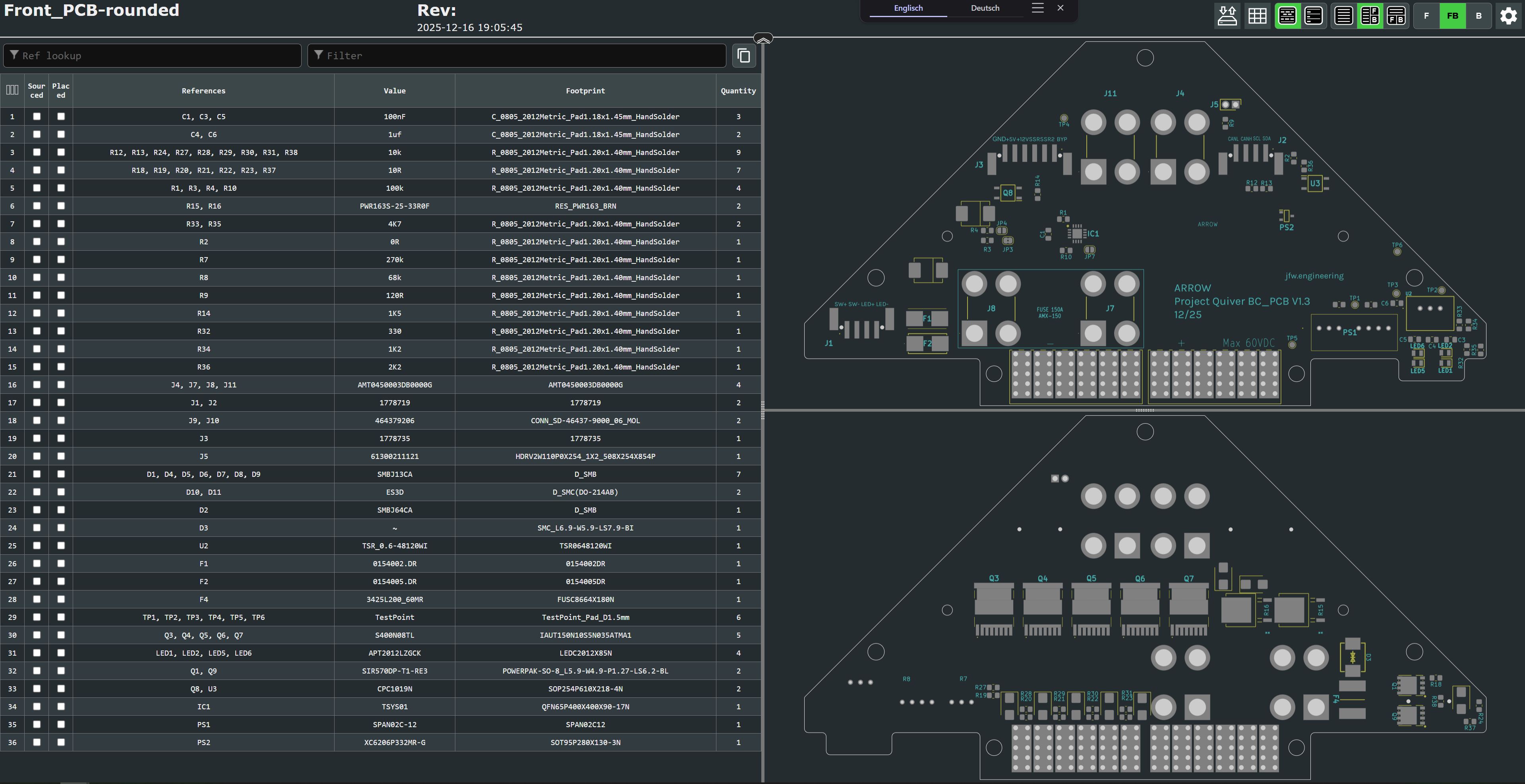
This is an HTML file that opens in the browser. On the left side is the parts list and on the right side are the views for the front and back of the circuit board. It will help to put the components in the right place.
It is essential to use a pcb stencil to place the solder paste in the right places. A reflow oven or a hot air blower (temperature and airflow controllable) should be used for the soldering process.
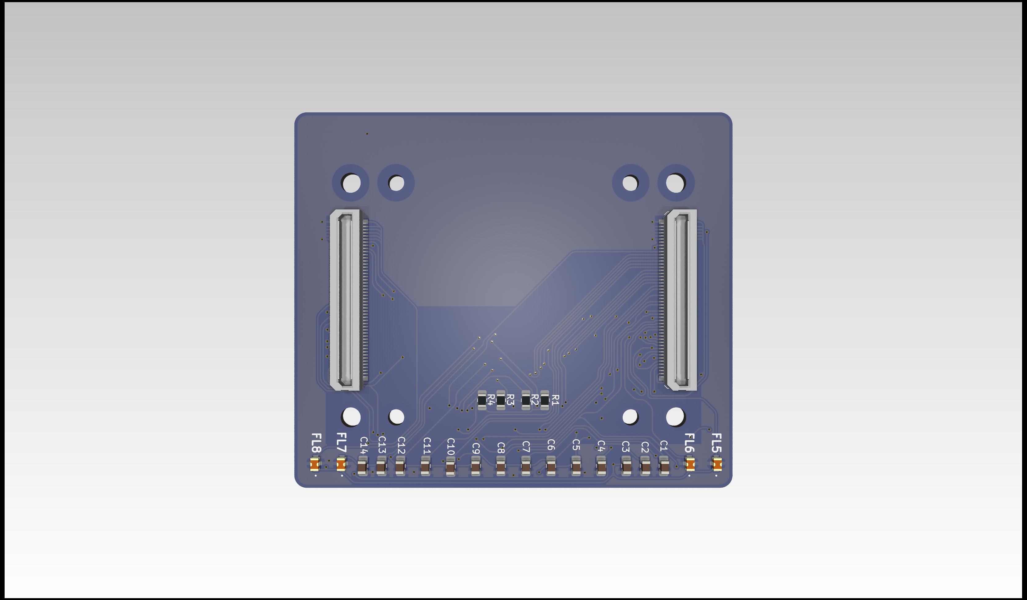
View on the top side of this PCB:
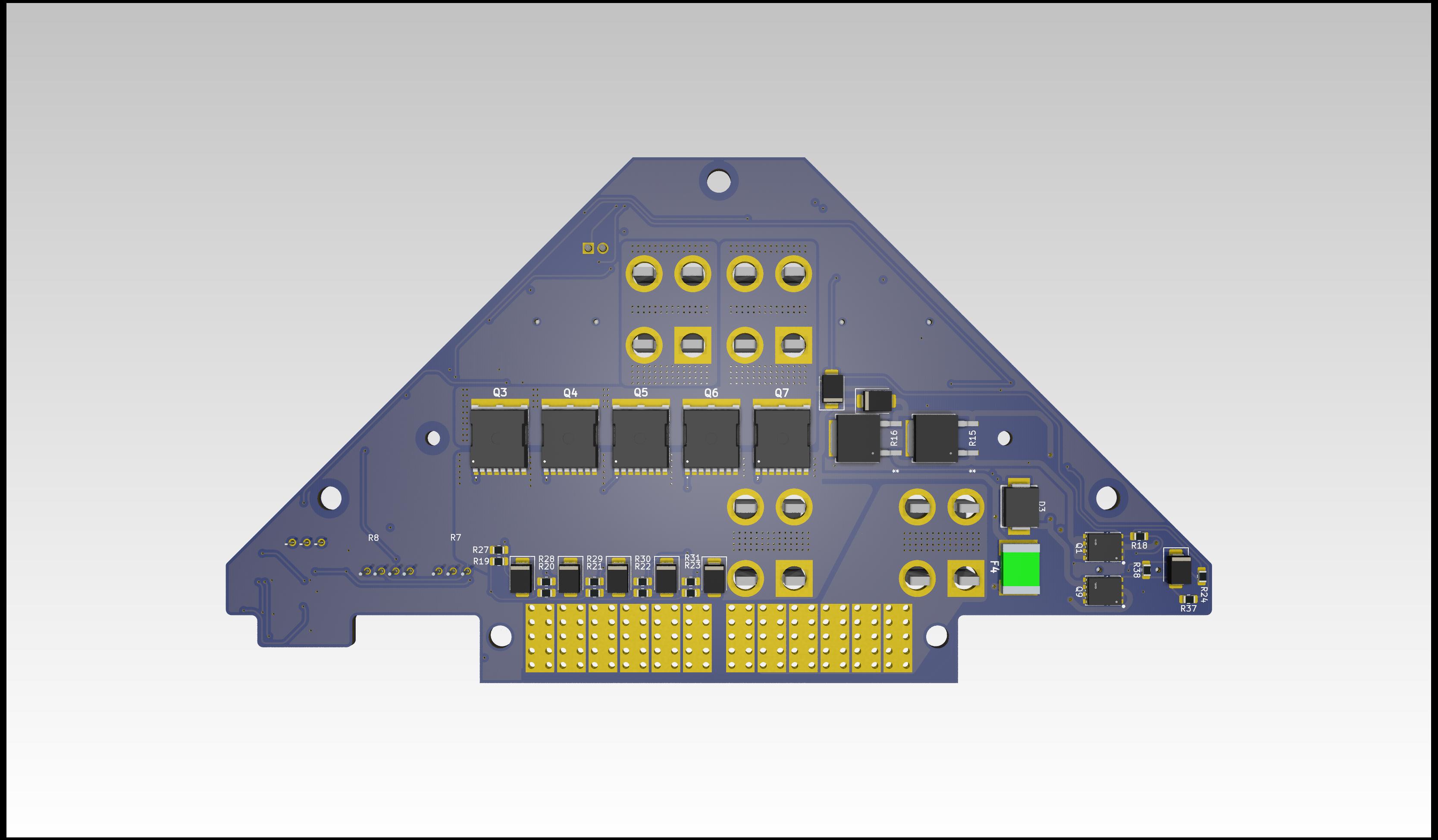
View on the bottom side of this PCB:
Additional Steps
1. Adding the Molex battery connector (J9, J10):
The molex battery connector can not be bought in one piece at the moment (12/25). It's assembled from four individual parts (1x guiding pin left, 1x guiding pin right, 2x Molex 46437-9206). The guiding pins are sourced from a pre assembled Molex connector 464379-301. The individual parts can be clipped together and then inserted into the PCB. The connector pins should be manually soldered to the PCB.
Picture:PCB with Molex connector
2. Installation of the heatsink:
The heatsink must be attached to the PCB for the PCB to function properly. The heat sink is in direct contact with the frame of the drone and ensures that the power mosfets are well cooled.
- Gap filler: Arctic TP-3 thermal pad: https://www.arctic.de/TP-3/ACTPD00057A
- Nylon spacers: McMaster 99072A104
- Screws: McMaster 92125A090
- Washers: McMaster 95610A011
- Nuts: McMaster 90591A270
Please secure the screws of the heatsink with loctite.
Picture: Thermal pad area and nylon spacer location
Picture: Screwed down heatsink
3. Installation of the fuse:
A AMX-200 fuse needs to be mounted between J7 and J8. Please use loctite to secure the screws.
Example screws: McMaster 98093A213
Flight Controller PCB
This chapter will help with the project Quiver FC PCB (Flight controller PCB) assembly process.
[!Note] This is not a final version of this document. The given instructions will give a general guide on the assembly process. Assembly should only be carried out by an experienced worker with experience in SMD soldering and the appropriate equipment. If you need this PCB fully assembled please contact the project Quiver team.
This PCB can be ordered fully assembled from the respective PCB manufacturer (e.g. JLCPCB). The 100 pin connectors (J1, J2, J3) are normally not in stock and must be ordered from the manufacturer. This means that the production time for a finished PCB is around 3 weeks.
The manual soldering of the circuit board can be done with the help of this interactive BOM which is stored in the respective github folder of this PCB(it is not recommended):
Quiver_PT3_FC_PCB_ibom.html
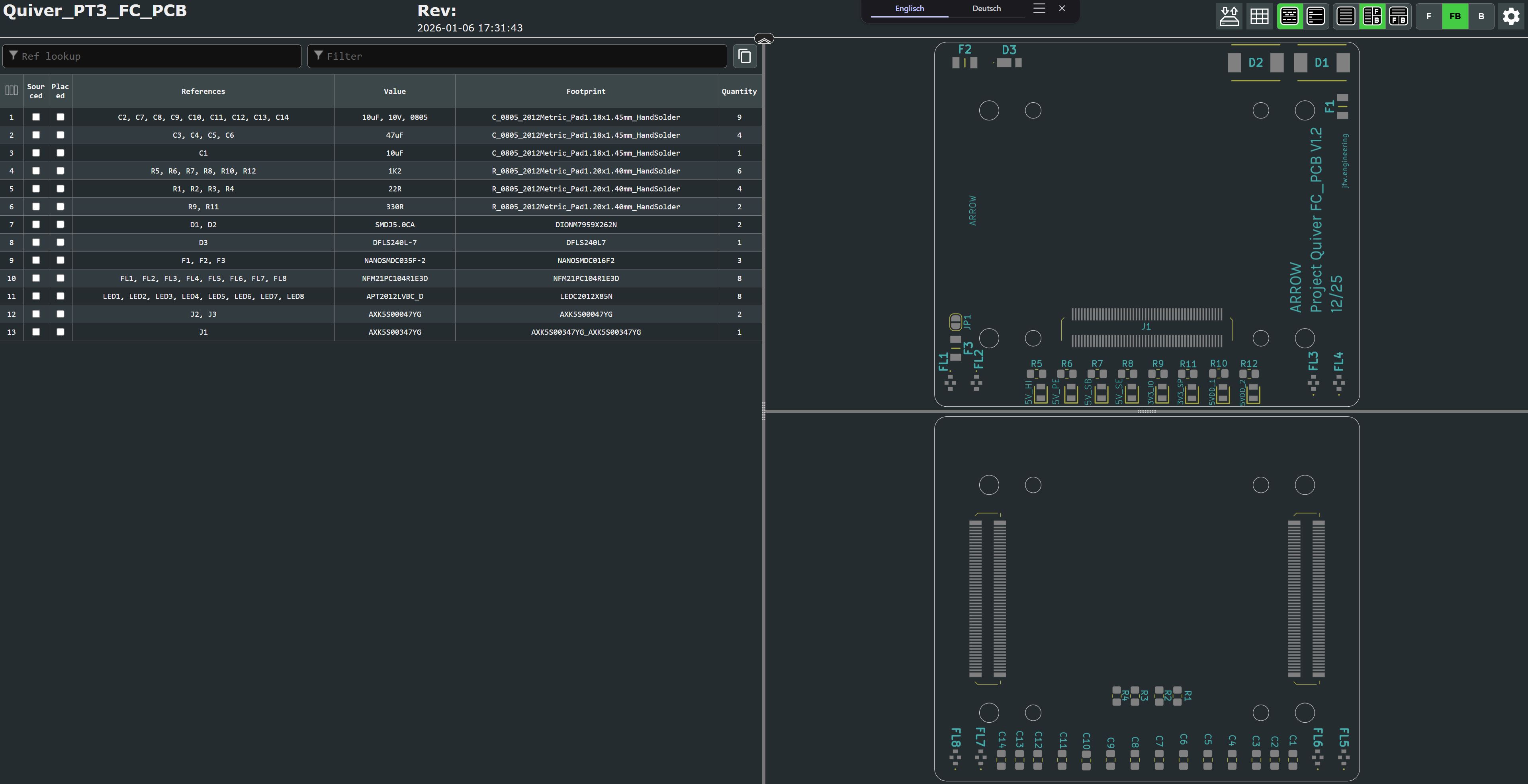
This is an HTML file that opens in the browser. On the left side is the parts list and on the right side are the views for the front and back of the circuit board. It will help to put the components in the right place.
It is essential to use a pcb stencil to place the solder paste in the right places. A reflow oven or a hot air blower (temperature and airflow controllable) should be used for the soldering process.
View on the top side of this PCB (this side will connect to the pix32 v6 flight controller):
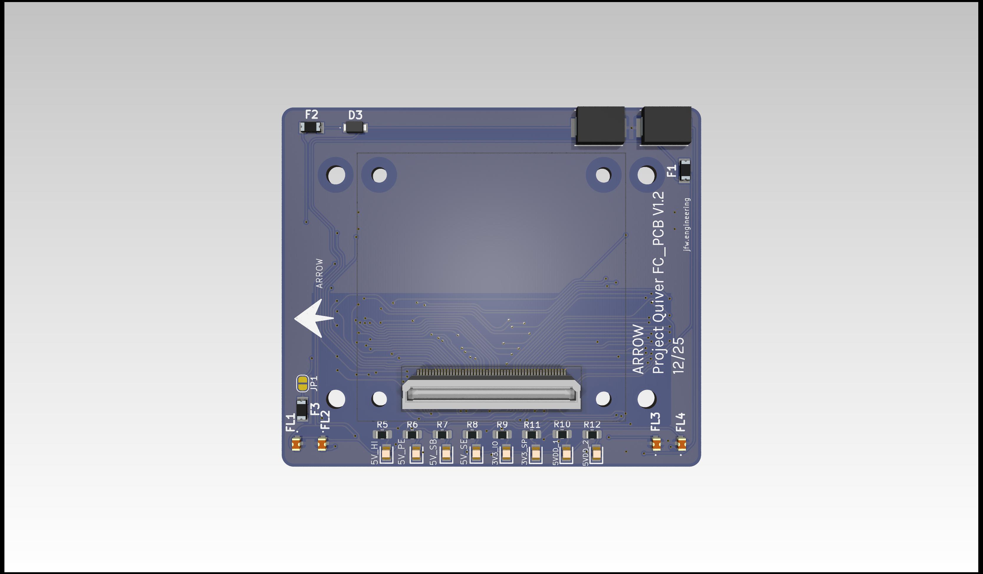
View on the bottom side of this PCB (this side will connect to the PT3 Main PCB):
Additional Steps
- no additional steps are needed.
Harness Manufacturing Guide
Purpose
This chapter explains how to manufacture and assemble the wiring harnesses for all of the components present on the dev kit build. Modifications include custom cut spool cables, pre made cables, pre crimped cables, and reducing length of default connectors.
Use the following wiring table for all of the connections TO/FROM for all of the dev kit’s systems: Dev Kit Wire Data The spreadsheet gives the full view of all connectors, mating connectors, wire gauge, estimated length, and suggested/default wire colors.
How To Use This Guide
This guide will detail the manufacturing process for all harnesses in no particular order. It is intended to be broken up and placed in the manufacturing guide according to the Quiver assembly steps. This is to allow harness routing that may be blocked by the installation of certain structural components. The user is encouraged to treat this document as a knowledge base and prep guide for the harnessing. Installation steps will be covered in the broader assembly guide.
Tools Required
- Soldering iron with hot air rework station
- Solder
- Wire stripper
- Wire cutter
- Heat shrink
- Heat shrink solder connectors
- Flathead screwdriver (1.5mm)
- Pliers
- Multimeter
Quality Assurance (QC) Checklist
- Visual: Check for exposed strands or damaged insulation.
- Mechanical: Pull-test all crimps lightly to ensure retention.
- Continuity: Probe Pin 1 to Pin 1 (Tone check).
- Polarity: Verify Red is Positive, Black is Ground.
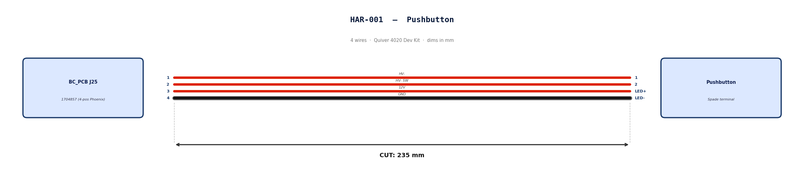
HAR-0001 Pushbutton
| FROM | TO |
|---|---|
| BC_PCB J25 | Pushbutton |
1. Nailboard
2. Bill of Materials (Kitting)
Gather these parts before starting the build.
| Item Type | Part Number | Description / Spec | Qty Needed |
|---|---|---|---|
| Connector A | 1704857 | 4-Pos Phoenix | 1 |
| Terminals A | Wire | Bare wire, twisted end | 4 |
| Connector B | Spade | Spade terminal | 4 |
| Terminals B | Wire | Bare wire | 4 |
| Wire | 18 AWG | Silicon | 940mm |
| Sleeving | Optional | Mesh | 180 mm |
3. Wire Prep (Cut & Strip)
Prepare all wires before assembly.
| Wire ID | Color | Gauge | Cut Length | Strip A | Strip B |
|---|---|---|---|---|---|
| W1 | Red | 18 AWG | 235mm | 6mm | 6mm |
| W2 | Red | 18 AWG | 235mm | 6mm | 6mm |
| W3 | Red | 18 AWG | 235mm | 6mm | 6mm |
| W4 | Black | 18 AWG | 235mm | 6mm | 6mm |
4. Termination & Pinout Map
Connect End A to End B following this chart.
| Wire ID | Color | From: 1704857 | To: Spade | Function / Signal |
|---|---|---|---|---|
| W1 | Red | Pin 1 | 1 | HV- |
| W2 | Red | Pin 2 | 2 | HV- SW |
| W3 | Red | Pin 3 | LED+ | 12V |
| W4 | Black | Pin 4 | LED- | GND |
5. Assembly Instructions
- Prep: Cut wires to length and strip insulation per Section 3.
- Label: Install identification markers per Section 5. Do not shrink yet.
- Populate A: Insert contacts into Connector A housing. Verify "Click" and perform pull-back test.
- Crimp Side B: Terminate Side B using crimping tool.
- Populate B: Insert contacts into Connector B housing.
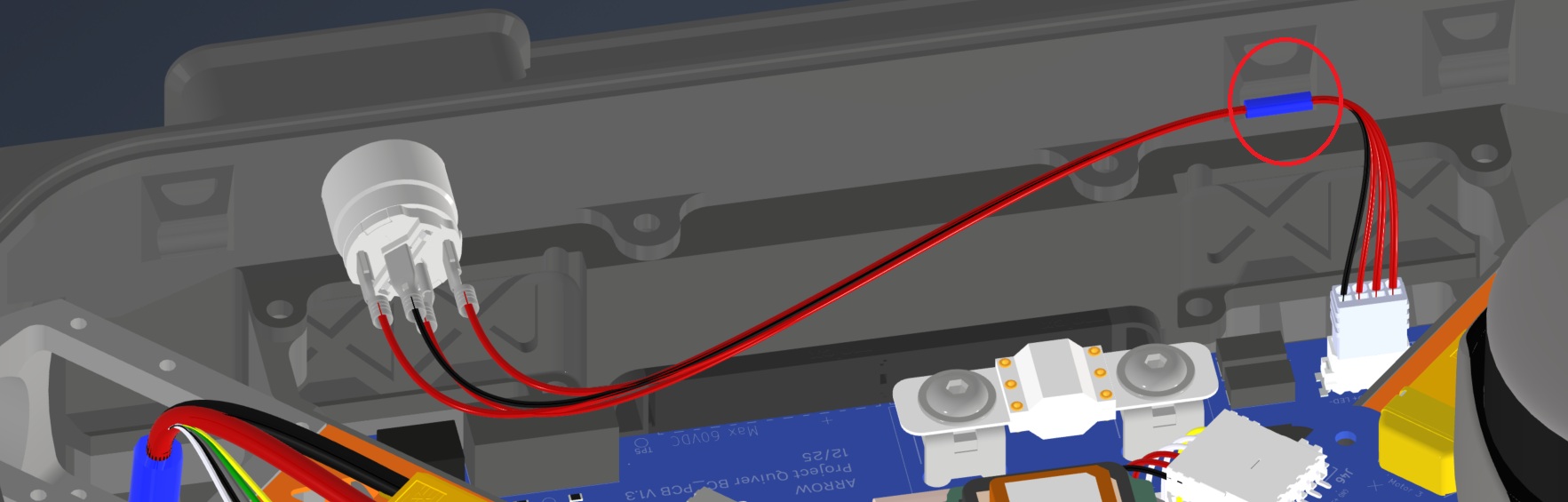
6. Installation & Routing (Vehicle Integration)
Instructions for the technician installing this harness into the chassis.
- Source Connection: Bat_PCB, J1
- Destination Connection: Pushbutton
- Routing Path:
- Path - Over Battery PCB
- Constraint - N/A
- Fixing - Zip Tie Provision Circled in red
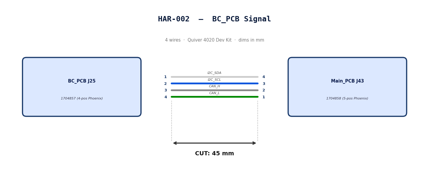
HAR-0002 BC_PCB Signal
| FROM | TO |
|---|---|
| BC_PCB J25 | Main_PCB J43 |
1. Nailboard
2. Bill of Materials (Kitting)
Gather these parts before starting the build.
| Item Type | Part Number | Description / Spec | Qty Needed |
|---|---|---|---|
| Connector A | 1704857 | 4-Pos Phoenix | 1 |
| Terminals A | Wire | Bare wire, twisted end | 4 |
| Connector B | 1704858 | 5-Pos Phoenix | 1 |
| Terminals B | Wire | Bare wire, twisted end | 4 |
| Wire | 20 AWG | Silicon | 240mm |
| Sleeving | Optional | Mesh | N/A |
3. Wire Prep (Cut & Strip)
Prepare all wires before assembly.
| Wire ID | Color | Gauge | Cut Length | Strip A | Strip B |
|---|---|---|---|---|---|
| W1 | White | 20 AWG | 56mm | 6mm | 6mm |
| W2 | Blue | 20 AWG | 56mm | 6mm | 6mm |
| W3 | Gray | 20 AWG | 56mm | 6mm | 6mm |
| W4 | Green | 20 AWG | 56mm | 6mm | 6mm |
4. Termination & Pinout Map
Connect End A to End B following this chart.
| Wire ID | Color | From: 1704857 | To: 1704858 | Function / Signal |
|---|---|---|---|---|
| W1 | White | Pin 1 | 4 | I2C_SDA |
| W2 | Blue | Pin 2 | 3 | I2C_SCL |
| W3 | Gray | Pin 3 | 2 | CAN_H |
| W4 | Green | Pin 4 | 1 | CAN_L |
5. Assembly Instructions
- Prep: Cut wires to length and strip insulation per Section
- Populate A: Insert contacts into Connector A housing. Verify "Click" and perform pull-back test.
- Populate B: Insert contacts into Connector B housing.Verify "Click" and perform pull-back test.
6. Installation & Routing (Vehicle Integration)
Instructions for the technician installing this harness into the chassis.*
- Source Connection: Bat_PCB, J2
- Destination Connection: Main_PCB, J43
- Routing Path:
- Path - N/A
- Constraint - N/A
- Fixing - N/A
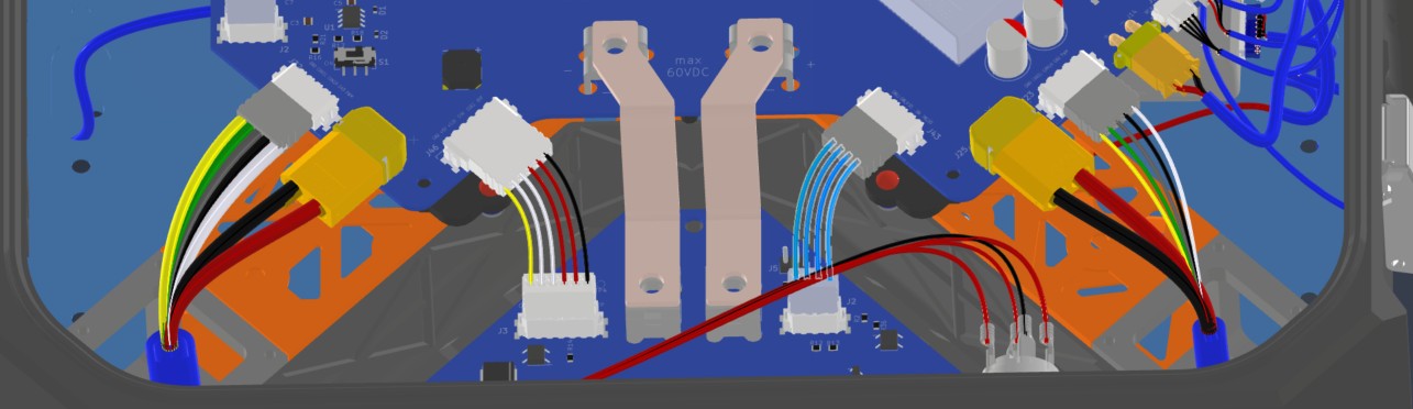
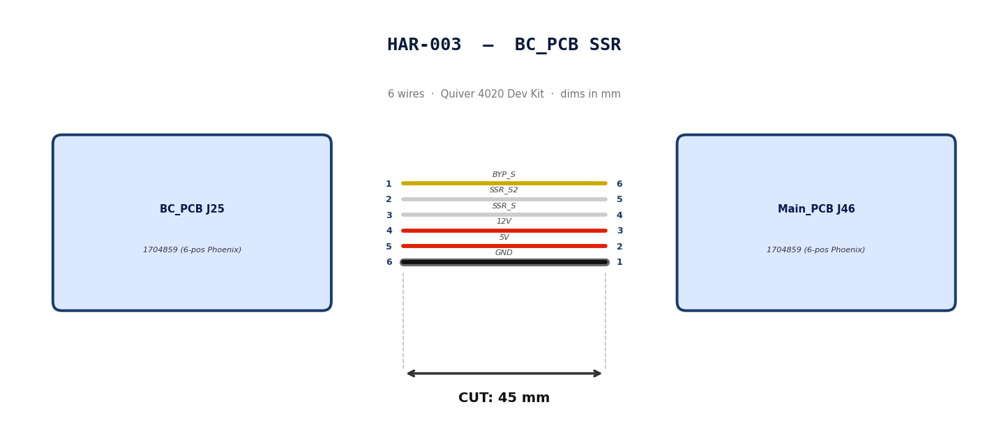
HAR-0003 BC_PCB SSR
| FROM | TO |
|---|---|
| BC_PCB J25 | Main_PCB J46 |
1. Nailboard
2. Bill of Materials (Kitting)
Gather these parts before starting the build.
| Item Type | Part Number | Description / Spec | Qty Needed |
|---|---|---|---|
| Connector A | 1704859 | 6-Pos Phoenix | 1 |
| Terminals A | Wire | Bare wire, twisted end | 6 |
| Connector B | 1704859 | 6-Pos Phoenix | 1 |
| Terminals B | Wire | Bare wire, twisted end | 6 |
| Wire | 20 AWG | Silicon | 50mm |
| Sleeving | Optional | Mesh | xx mm |
3. Wire Prep (Cut & Strip)
Prepare all wires before assembly.
| Wire ID | Color | Gauge | Cut Length | Strip A | Strip B |
|---|---|---|---|---|---|
| W1 | Yellow | 20 AWG | 56mm | 6mm | 6mm |
| W2 | White | 20 AWG | 56mm | 6mm | 6mm |
| W3 | White | 20 AWG | 56mm | 6mm | 6mm |
| W4 | Red | 20 AWG | 56mm | 6mm | 6mm |
| W5 | Red | 20 AWG | 56mm | 6mm | 6mm |
| W6 | Black | 20 AWG | 56mm | 6mm | 6mm |
4. Termination & Pinout Map
Connect End A to End B following this chart.
| Wire ID | Color | From: 1704859 | To: 1704859 | Function / Signal |
|---|---|---|---|---|
| W1 | Yellow | Pin 1 | 6 | BYP_S |
| W2 | White | Pin 2 | 5 | SSR_S2 |
| W3 | White | Pin 3 | 4 | SSR_S |
| W4 | Red | Pin 4 | 3 | 12V |
| W5 | Red | Pin 5 | 2 | 5V |
| W6 | Black | Pin 6 | 1 | GND |
5. Assembly Instructions
- Prep: Cut wires to length and strip insulation per Section
- Populate A: Insert contacts into Connector A housing. Verify "Click" and perform pull-back test.
- Populate B: Insert contacts into Connector B housing.Verify "Click" and perform pull-back test.
6. Installation & Routing (Vehicle Integration)
Instructions for the technician installing this harness into the chassis.
- Source Connection: Bat_PCB, J3
- Destination Connection: Main_PCB, J46
- Routing Path:
- Path -
- Constraint -
- Fixing -
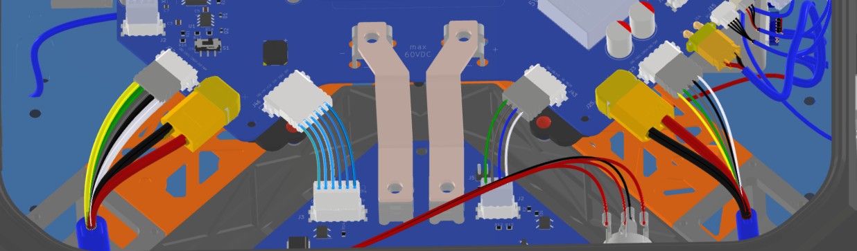
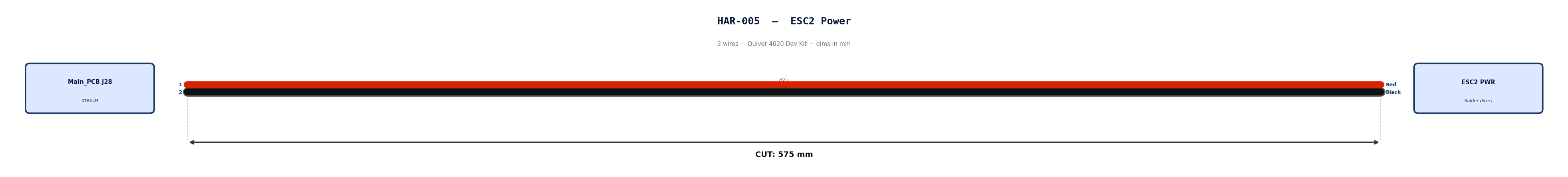
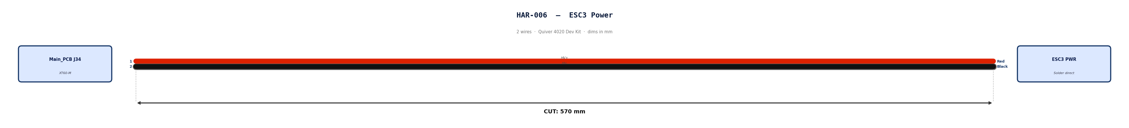
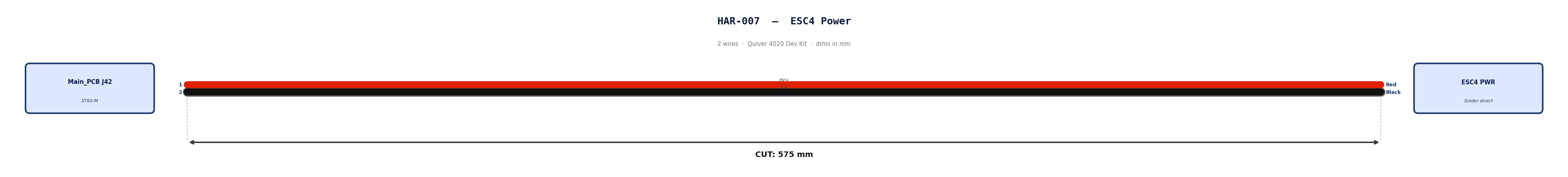
HAR-0004 -> HAR-007 ESC Power
| FROM | TO |
|---|---|
| Main_PCB J25 | ESC1 PWR |
| Main_PCB J28 | ESC2 PWR |
| Main_PCB J34 | ESC3 PWR |
| Main_PCB J42 | ESC4 PWR |
1. Nailboard

2. Bill of Materials (Kitting)
Gather these parts before starting the build.
| Item Type | Part Number | Description / Spec | Qty Needed |
|---|---|---|---|
| Connector A | XT60-M | 2-Pos XT-60 | 1 |
| Terminals A | Wire | Solder | 2 |
| Wire | 6 AWG | Silicon | 490mm |
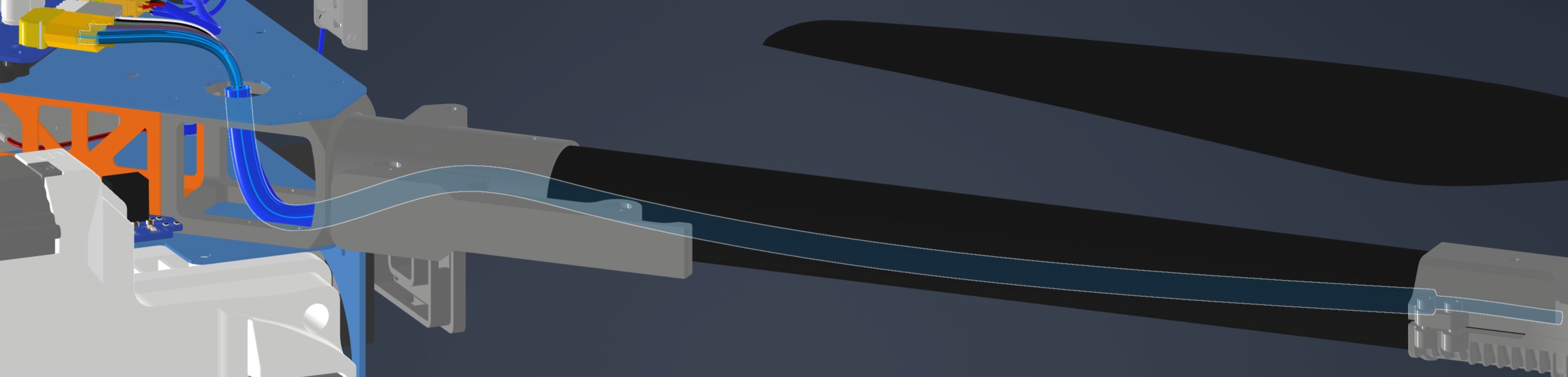
| Sleeving | Required | 9.5mm ID heatshrink at motor arm bend | 7cm |
3. Wire Prep (Cut & Strip)
Prepare all wires before assembly.
| Wire ID | Color | Gauge | Cut Length | Strip A | Strip B |
|---|---|---|---|---|---|
| W1 | Red | 6 AWG | 490mm | 4mm | N/A |
| W2 | Black | 6 AWG | 490mm | 4mm | N/A |
4. Termination & Pinout Map
Connect End A to End B following this chart.
| Wire ID | Color | From: XT60-M | To: ESC1 | Function / Signal |
|---|---|---|---|---|
| W1 | Red | Pin 1 | Red | HV+ |
| W2 | Black | Pin 2 | Black | HV- |
6. Assembly Instructions (Not finished)
- Prep: Cut wires to length and strip insulation per Section 3.
- Populate A: Solder cables into Connector A housing.
- Heatshrink: Apply a 7cm 9.5mm ID heatshrink at the motor arm bend location. This heatshrink will protect the ESC Power and signal cables*
7. Installation & Routing (Vehicle Integration)
Instructions for the technician installing this harness into the chassis.
- Source Connection: Main_PCB, J27
- Destination Connection: ESC 1 PWR
- Routing Path:
- Path - Through circular hole on upper plate to middle plate
- Constraint - N/A
- Fixing - N/A
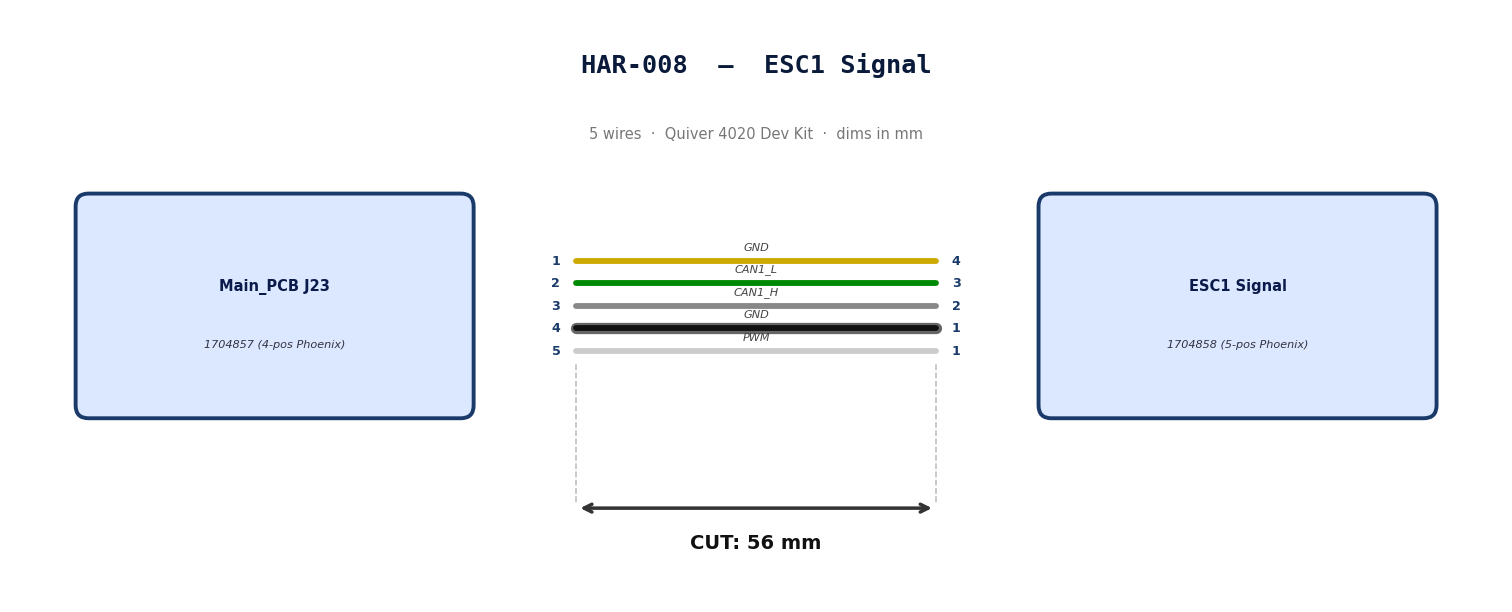
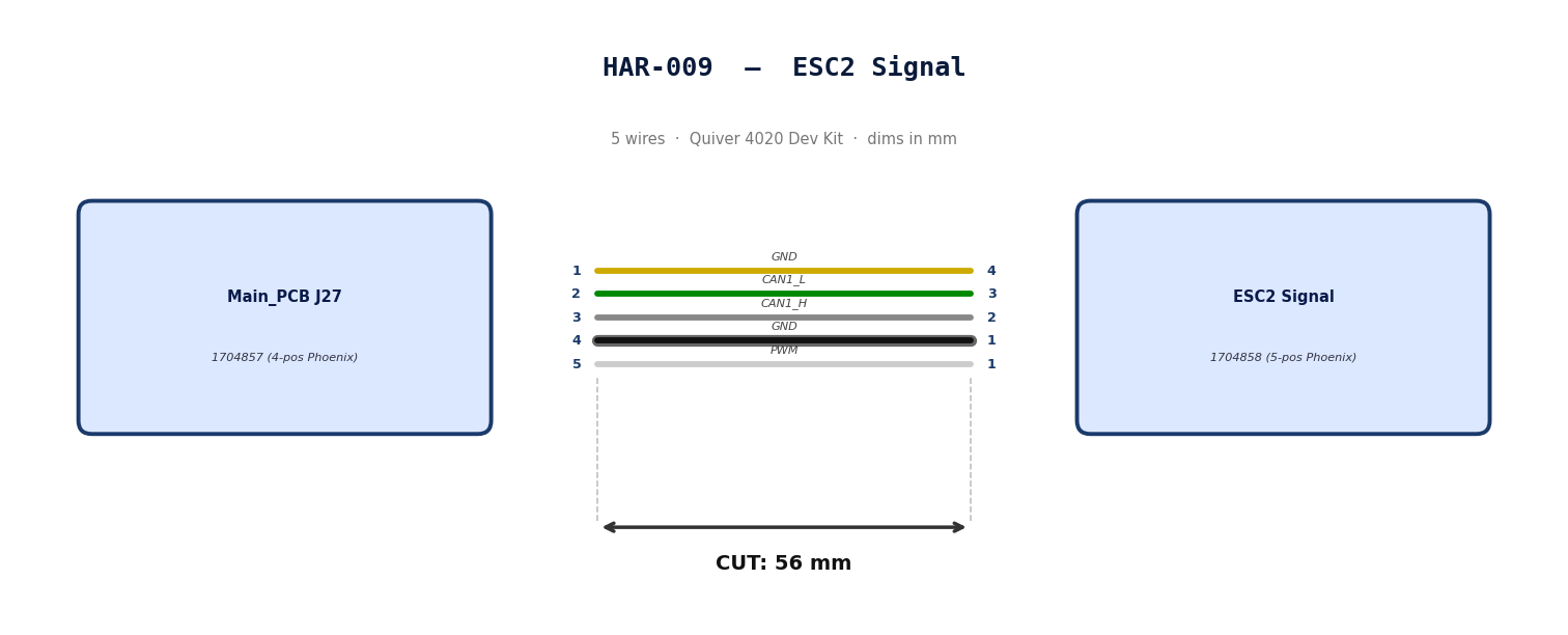
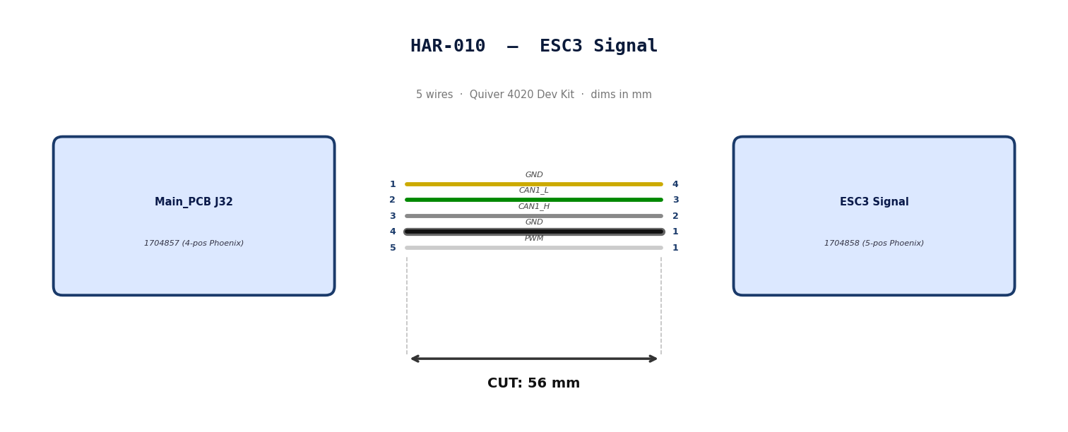
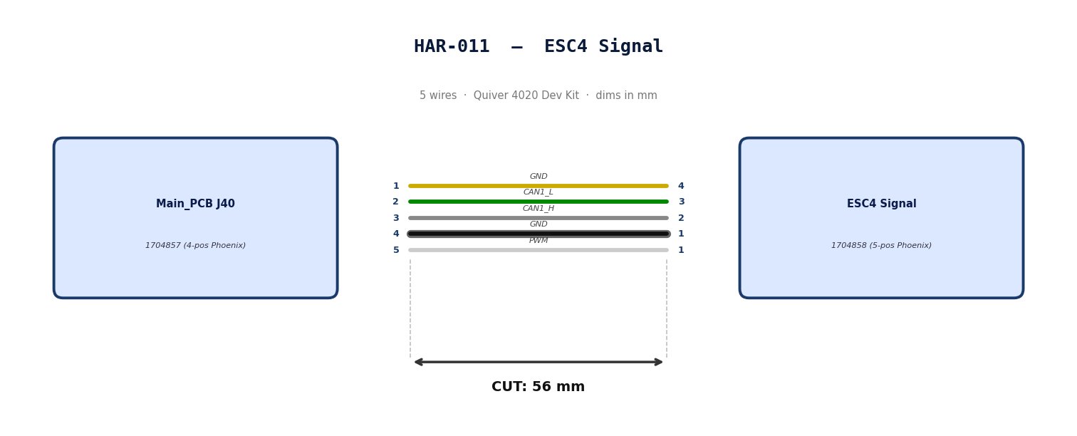
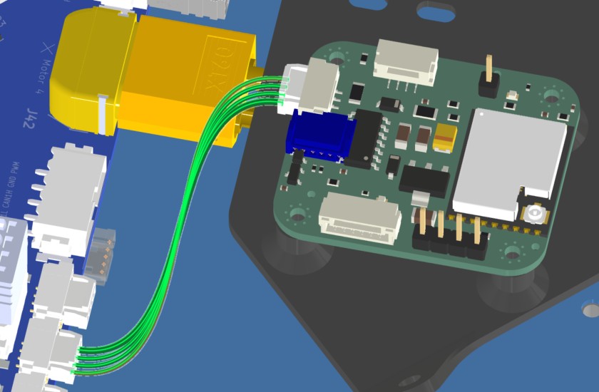
HAR-0008 -> HAR-0011
| FROM | TO |
|---|---|
| Main_PCB J23 | ESC1 Signal |
| Main_PCB J27 | ESC2 Signal |
| Main_PCB J32 | ESC3 Signal |
| Main_PCB J40 | ESC4 Signal |
1. Nailboard
2. Bill of Materials (Kitting)
Gather these parts before starting the build.
| Item Type | Part Number | Description / Spec | Qty Needed |
|---|---|---|---|
| Connector A | 1704858 | 5-Pos Phoenix | 1 |
| Terminals A | Wire | Bare wire, twisted end | 5 |
| Wire | 20 AWG | Silicon | 240mm |
| Sleeving | Required | 9.5mm ID Heatshrink at motor arm bend | 7cm |
3. Wire Prep (Cut & Strip)
Prepare all wires before assembly.
| Wire ID | Color | Gauge | Cut Length | Strip A | Strip B |
|---|---|---|---|---|---|
| W1 | Yellow | 20 AWG | 56mm | 6mm | 6mm |
| W2 | Green | 20 AWG | 56mm | 6mm | 6mm |
| W3 | Gray | 20 AWG | 56mm | 6mm | 6mm |
| W4 | Black | 20 AWG | 56mm | 6mm | 6mm |
| W5 | White | 20 AWG | 56mm | 6mm | 6mm |
4. Termination & Pinout Map
Connect End A to End B following this chart.
| Wire ID | Color | From: 1704857 | To: 1704858 | Function / Signal |
|---|---|---|---|---|
| W1 | Yellow | Pin 1 | 4 | GND |
| W2 | Green | Pin 2 | 3 | CAN1_L |
| W3 | Gray | Pin 3 | 2 | CAN1_H |
| W4 | Black | Pin 4 | 1 | GND |
| W5 | White | Pin 5 | 1 | PWM |
5. Assembly Instructions
- Prep: Cut wires to length and strip insulation per Section
- Populate A: Insert contacts into Connector A housing. Verify "Click" and perform pull-back test.
- Heatshrink: Apply a 7cm 9.5mm ID Heatshrink at the motor arm bend location. This heatshrink will protect the ESC Power and signal cables*
6. Installation & Routing (Vehicle Integration)
Instructions for the technician installing this harness into the chassis.*
- Source Connection: Bat_PCB, J2
- Destination Connection: Main_PCB, J43
- Routing Path:
- Path - N/A
- Constraint - N/A
- Fixing - N/A
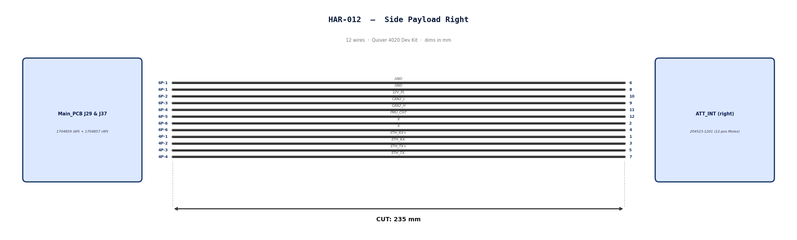
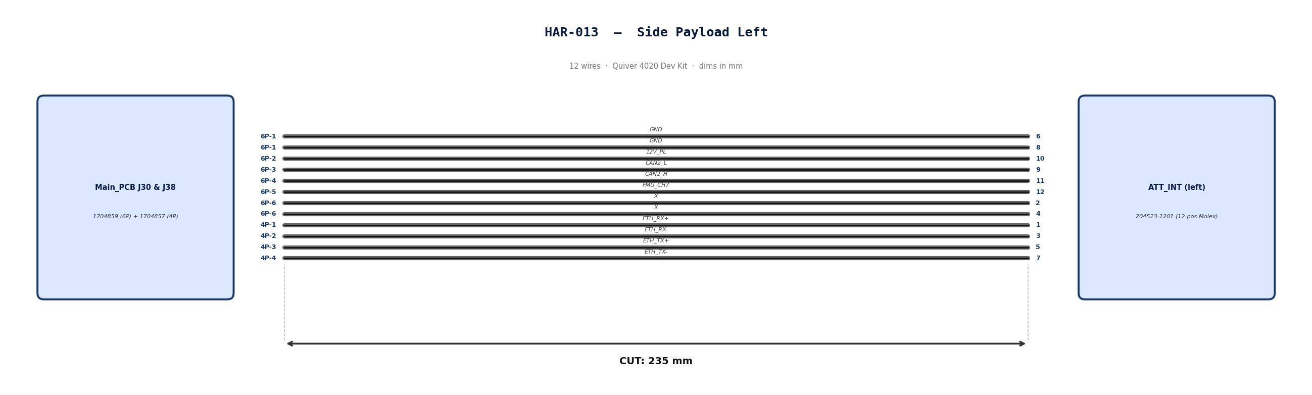
HAR-0012 -> HAR-0013 Side Payloads
| FROM | TO |
|---|---|
| Main_PCB J29, J37 | ATT_INT (right) |
| Main_PCB J30, J38 | ATT_INT (left) |
1. Nailboard
2. Bill of Materials (Kitting)
Gather these parts before starting the build.
| Item Type | Part Number | Description / Spec | Qty Needed |
|---|---|---|---|
| Connector A | 1704859 | 6-Pos Phoenix | 1 |
| Terminals A | Wire | Pre-crimped | 8 |
| Connector B | 1704857 | 4-Pos Phoenix | 1 |
| Terminals B | Wire | Pre-crimped | 4 |
| Connector C | 204523-1201 | 12-Pos Molex | 1 |
| Terminals C | Wire | Pre-crimped | 12 |
| Wire | 26 AWG | Pre-Crimped Lead | 235mm |
| Sleeving | Optional | Mesh | xx mm |
3. Wire Prep (Cut & Strip)
All wires connecting the payload to the PCBs will use pre-crimped jumper wires. Mouser #: 538-79758-1149
| Wire ID | Color | Gauge | Cut Length | Strip A | Strip B |
|---|---|---|---|---|---|
| W1 | Black | 26 | 235mm | N/A | N/A |
| W2 | Black | 26 | 235mm | N/A | N/A |
| W3 | Black | 26 | 235mm | N/A | N/A |
| W4 | Black | 26 | 235mm | N/A | N/A |
| W5 | Black | 26 | 235mm | N/A | N/A |
| W6 | Black | 26 | 235mm | N/A | N/A |
| W7 | Black | 26 | 235mm | N/A | N/A |
| W8 | Black | 26 | 235mm | N/A | N/A |
| W9 | Black | 26 | 235mm | N/A | N/A |
| W10 | Black | 26 | 235mm | N/A | N/A |
| W11 | Black | 26 | 235mm | N/A | N/A |
| W12 | Black | 26 | 235mm | N/A | N/A |
4. Termination & Pinout Map
Connect End A or B to End C following this chart.
| Wire ID | Color | From: 1704859 | To: 204523-1201 | Function / Signal |
|---|---|---|---|---|
| W1 | Black | Pin 1 | 6 | GND |
| W2 | Black | Pin 1 | 8 | GND |
| W3 | Black | Pin 2 | 10 | 12V_PL |
| W4 | Black | Pin 3 | 9 | CAN2_L |
| W5 | Black | Pin 4 | 11 | CAN2_H |
| W6 | Black | Pin 5 | 12 | FMU_CH7 |
| W7 | Black | Pin 6 | 2 | X |
| W8 | Black | Pin 6 | 4 | X |
| Wire ID | Color | From: 1704857 | To: 204523-1201 | Function / Signal |
|---|---|---|---|---|
| W9 | Black | Pin 1 | 1 | ETH_RX+ |
| W10 | Black | Pin 2 | 3 | ETH_RX- |
| W11 | Black | Pin 3 | 5 | ETH_TX+ |
| W12 | Black | Pin 4 | 7 | ETH_TX- |
5. Assembly Instructions
- Populate A & B: Insert contacts into Connector A housing. Verify "Click" and perform pull-back test.
- Populate C: Insert contacts into Connector B housing. Verify correct crimp orientation into housing.
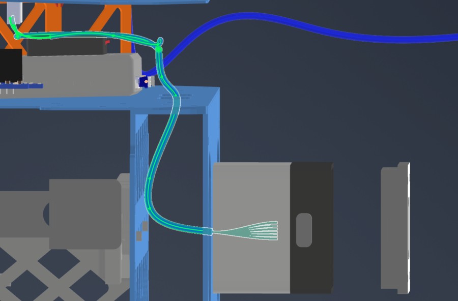
6. Installation & Routing (Vehicle Integration)
Instructions for the technician installing this harness into the chassis. Mirror the installation path for the payload on the opposite side.
- Source Connection: Main_PCB J29 & J37
- Destination Connection: ATT_INT (right)
- Routing Path:
- Path - Underneath MainPCB to middle plate side circular openings
- Constraint - Telemetry air unit location
- Fixing - N/A
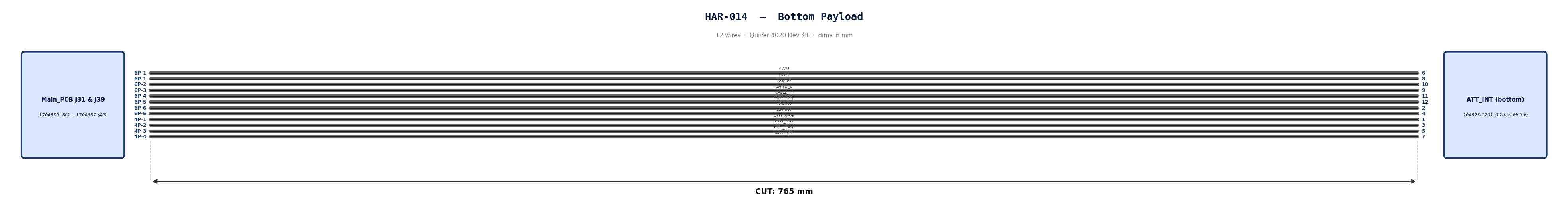
HAR-0014 Bottom Payload
| FROM | TO |
|---|---|
| Main_PCB J31, J39 | ATT_INT (bottom) |
1. Nailboard
2. Bill of Materials (Kitting)
Gather these parts before starting the build.
| Item Type | Part Number | Description / Spec | Qty Needed |
|---|---|---|---|
| Connector A | 1704859 | 6-Pos Phoenix | 1 |
| Terminals A | Wire | Pre-crimped | 8 |
| Connector B | 1704857 | 4-Pos Phoenix | 1 |
| Terminals B | Wire | Pre-crimped | 4 |
| Connector C | 204523-1201 | 12-Pos Molex | 1 |
| Terminals C | Wire | Pre-crimped | 12 |
| Wire | 26 AWG | Pre-Crimped Lead | 205mm |
| Sleeving | Optional | Mesh | xx mm |
3. Wire Prep (Cut & Strip)
All wires connecting the payload to the PCBs will use pre-crimped jumper wires. Mouser #: 538-79758-1149
Technician will have to combine two cables to create a 400mm cable.
Step 1: Cut to Length
-
Take two separate cable assemblies.
-
Measure 205mm from the back of the connector on the first cable.
-
Cut the wire at the 205mm mark. Discard the excess.
-
Repeat for the second cable.
- Note: We cut to 205mm (not 200mm) to allow 5mm of overlap for the splice, resulting in a final length of 400mm.
Step 2: Strip Insulation
-
Strip 5mm of insulation from the cut end of the first cable.
-
Strip 5mm of insulation from the cut end of the second cable.
Step 3: Insert Sleeve (Critical Step)
-
Before connecting the wires, slide the Self-Solder Heat Shrink Sleeve onto one of the cables.
-
Slide it at least 50mm down the wire so the heat from soldering doesn't shrink it prematurely.
Step 4: Mesh the Wires
-
Fan out the exposed strands of both cables slightly.
-
Push the two ends together so the strands interlace (mesh) with each other inline. Do not twist them side-by-side (pigtail).
-
Once meshed, twist the joined section to lock the strands together. The splice should be smooth and straight.
Step 5: Position the Sleeve
-
Slide the solder sleeve over the twisted joint.
-
Center the low-temperature solder ring directly over the bare copper twist.
-
Ensure the colored adhesive rings (at the ends of the sleeve) are covering the wire insulation, not the bare copper.
Step 6: Apply Heat
-
Using a heat gun, heat the center solder ring first. Watch for the solder to melt and flow into the wire strands (it will turn shiny and liquid).
-
Move the heat to the ends of the sleeve to shrink the tubing and activate the waterproof adhesive seals.
-
Allow to cool for 30 seconds before moving. Do not pull on the cable while the solder is hot.
Final Check
-
Total Length: Confirm the total length is 400mm.
-
Solder Joint: Ensure the solder ring has fully melted and is not visible as a solid ring anymore.
-
Insulation: Ensure there is no exposed copper outside the sleeve.
| Wire ID | Color | Gauge | Cut Length | Strip A | Strip B |
|---|---|---|---|---|---|
| W1 | Black | 26 | 400mm | N/A | N/A |
| W2 | Black | 26 | 400mm | N/A | N/A |
| W3 | Black | 26 | 400mm | N/A | N/A |
| W4 | Black | 26 | 400mm | N/A | N/A |
| W5 | Black | 26 | 400mm | N/A | N/A |
| W6 | Black | 26 | 400mm | N/A | N/A |
| W7 | Black | 26 | 400mm | N/A | N/A |
| W8 | Black | 26 | 400mm | N/A | N/A |
| W9 | Black | 26 | 400mm | N/A | N/A |
| W10 | Black | 26 | 400mm | N/A | N/A |
| W11 | Black | 26 | 400mm | N/A | N/A |
| W12 | Black | 26 | 400mm | N/A | N/A |
4. Termination & Pinout Map
Connect End A or B to End C following this chart.
| Wire ID | Color | From: 1704859 | To: 204523-1201 | Function / Signal |
|---|---|---|---|---|
| W1 | Black | Pin 1 | 6 | GND |
| W2 | Black | Pin 1 | 8 | GND |
| W3 | Black | Pin 2 | 10 | 12V_PL |
| W4 | Black | Pin 3 | 9 | CAN2_L |
| W5 | Black | Pin 4 | 11 | CAN2_H |
| W6 | Black | Pin 5 | 12 | FMU_CH7 |
| W7 | Black | Pin 6 | 2 | 12VSW |
| W8 | Black | Pin 6 | 4 | 12VSW |
| Wire ID | Color | From: 1704857 | To: 204523-1201 | Function / Signal |
|---|---|---|---|---|
| W9 | Black | Pin 1 | 1 | ETH_RX+ |
| W10 | Black | Pin 2 | 3 | ETH_RX- |
| W11 | Black | Pin 3 | 5 | ETH_TX+ |
| W12 | Black | Pin 4 | 7 | ETH_TX- |
5. Assembly Instructions
- Prep: Cut wires to length and strip insulation per Section 3.
- Label: Install identification markers to the cables. This will help correctly adding cables to Phoenix connector
- Populate A & B: Insert contacts into Connector A & B housing. Verify "Click" and perform pull-back test.
- Populate C: Insert contacts into Connector C housing. Verify correct crimp orientation into housing.
6. Installation & Routing (Vehicle Integration)
Instructions for the technician installing this harness into the chassis.
- Source Connection: Main_PCB J31 & J39
- Destination Connection: ATT INT (bottom)
- Routing Path:
- Path - Top Plate, right side opening, through mid plate openings, attached to the underside of the bottom plate
- Constraint - Number of cables passing through openings
- Fixing - Various zip ties show in red
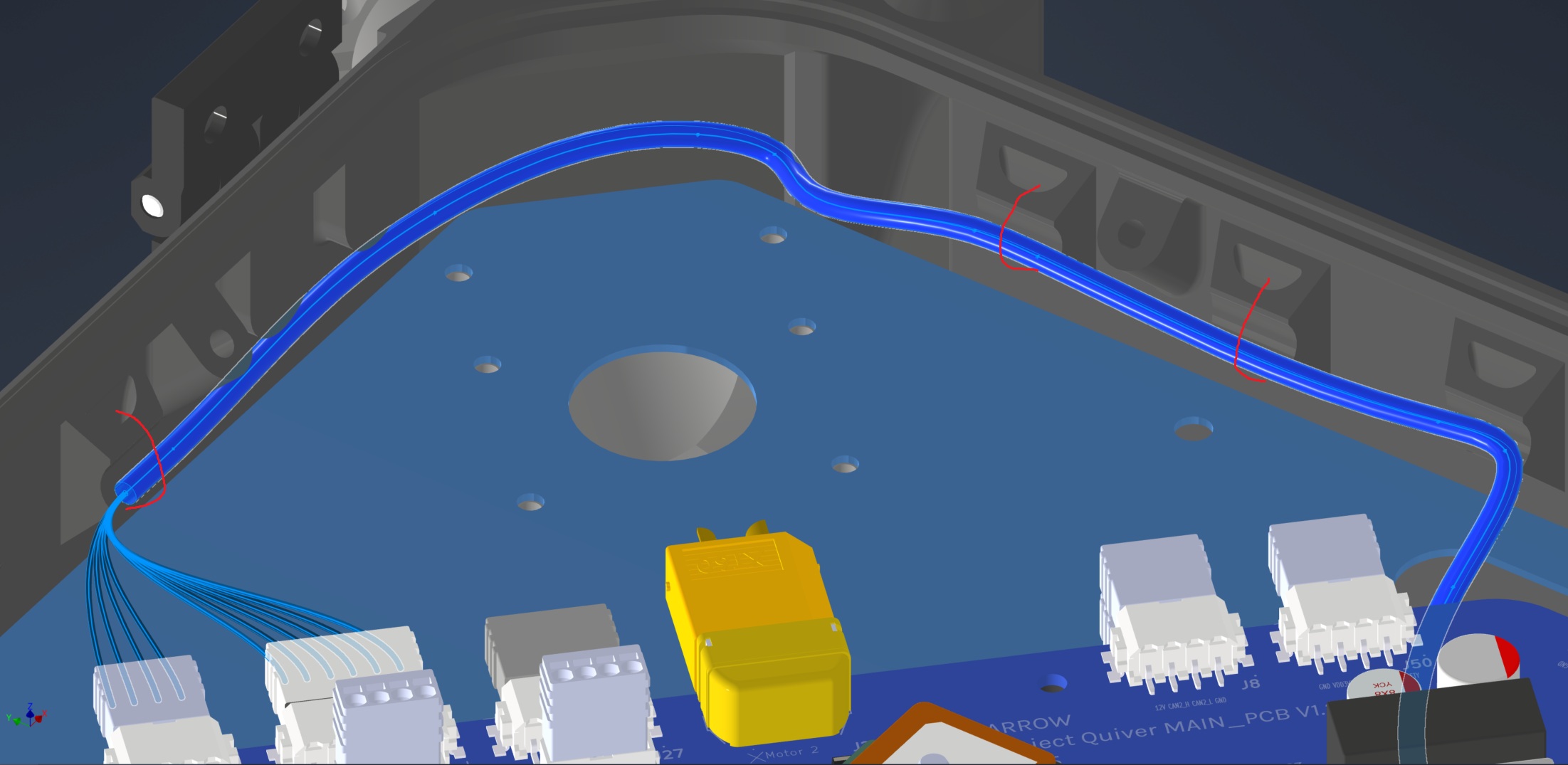
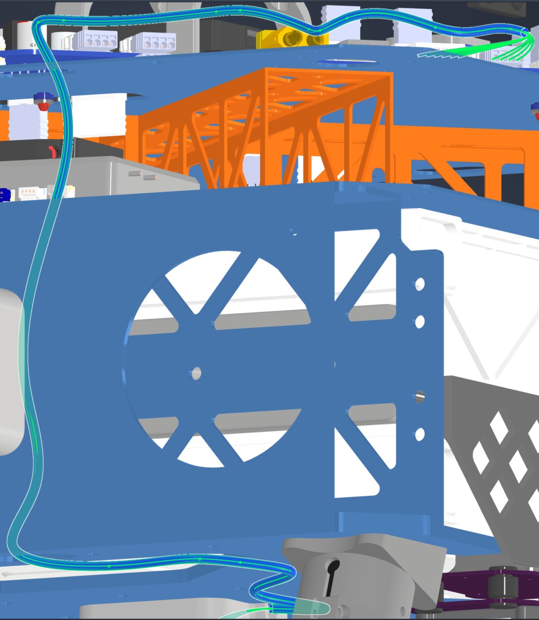
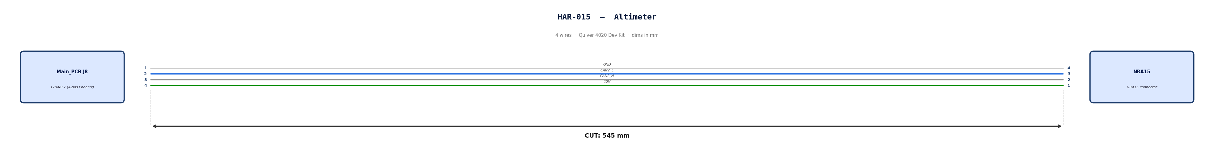
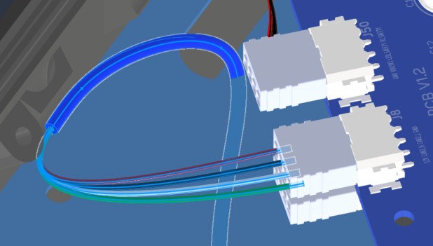
HAR-0015 Altimeter
| FROM | TO |
|---|---|
| Main_PCB J8 | NRA15 |
1. Nailboard
2. Bill of Materials (Kitting)
Gather these parts before starting the build.
| Item Type | Part Number | Description / Spec | Qty Needed |
|---|---|---|---|
| Connector A | 1704857 | 4-Pos Phoenix | 1 |
| Terminals A | Wire | Bare wire, twisted end | 4 |
| Wire | Default | Silicon | 190mm |
| Sleeving | Optional | Mesh | xx mm |
3. Wire Prep (Cut & Strip)
Prepare all wires before assembly.
| Wire ID | Color | Gauge | Cut Length | Strip A | Strip B |
|---|---|---|---|---|---|
| W1 | Default | Default | 190mm | 6mm | N/A |
| W2 | Default | Default | 190mm | 6mm | N/A |
| W3 | Default | Default | 190mm | 6mm | N/A |
| W4 | Default | Default | 190mm | 6mm | N/A |
4. Termination & Pinout Map
Connect End A to End B following this chart.
| Wire ID | Color | From: 1704857 | To: NRA 15 | Function / Signal |
|---|---|---|---|---|
| W1 | White | Pin 1 | 4 | GND |
| W2 | Blue | Pin 2 | 3 | CAN2_L |
| W3 | Gray | Pin 3 | 2 | CAN2_H |
| W4 | Green | Pin 4 | 1 | 12V |
5. Assembly Instructions
- Prep: Cut wires to length and strip insulation per Section 3.
- Crimp Side A: Terminate Side A using [Tool Name/Die].
- Populate A: Insert contacts into Connector A housing. Verify "Click" and perform pull-back test.
6. Installation & Routing (Vehicle Integration)
Instructions for the technician installing this harness into the chassis.
- Source Connection: Main PCB, J8
- Destination Connection: NRA 15
- Routing Path:
- Path - Right side top plate entry to bottom plate
- Constraint - other cables
- Fixing - Zip tie in red
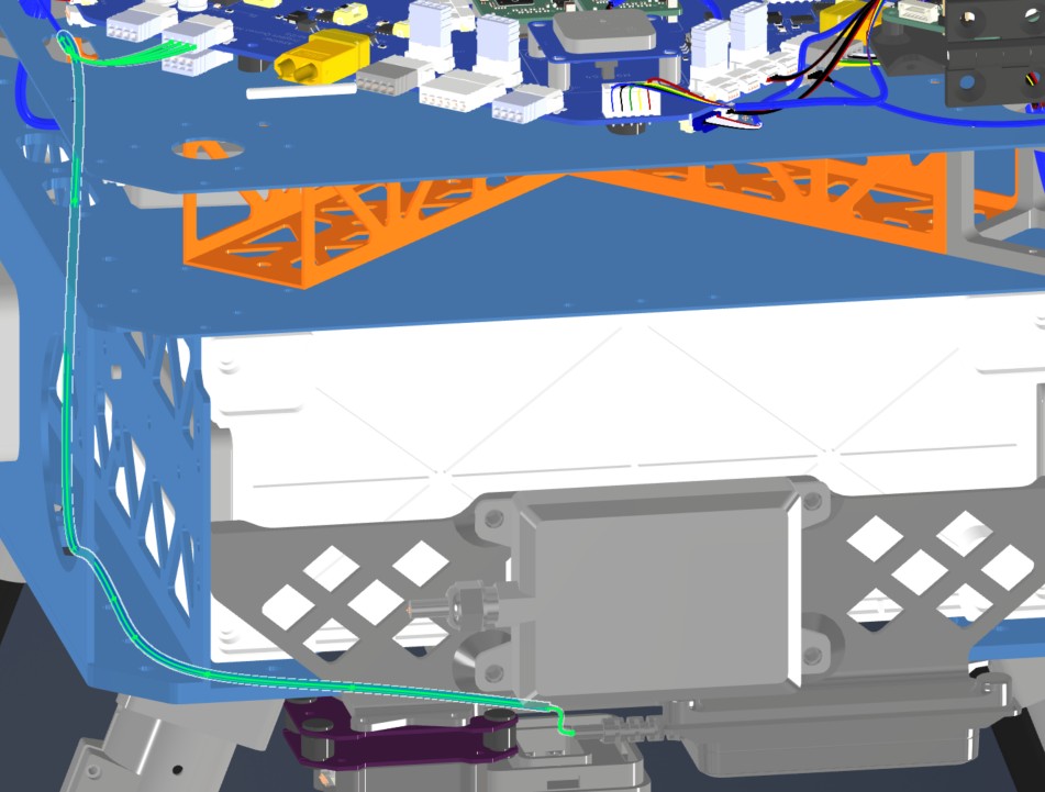
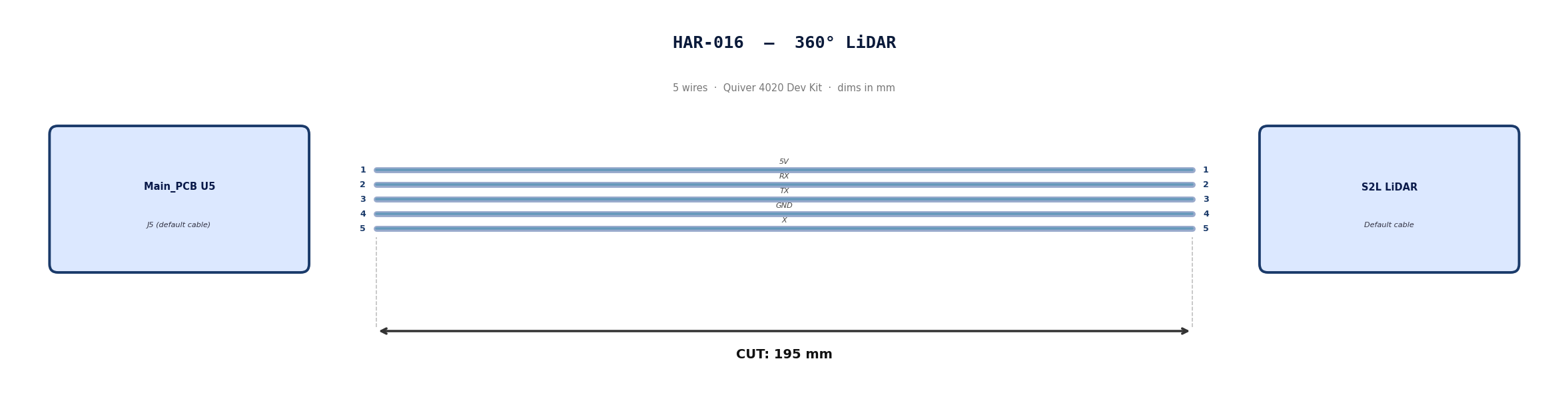
HAR-0016 360 LIDAR
| FROM | TO |
|---|---|
| Main_PCB U5 | S2l |
1. Nailboard
2. Bill of Materials (Kitting)
Default cable that comes with 360° Lidar. No modification required
3. Wire Prep (Cut & Strip)
Use the default cable supplied with the 360° LiDAR module.
| Cable | Required Length (mm) |
|---|---|
| Default LiDAR cable | 195 |
4. Termination & Pinout Map
Connect End A to End B following this chart.
| Wire ID | Color | From: J5 | To: NRA 15 | Function / Signal |
|---|---|---|---|---|
| W1 | Default | Pin 1 | 1 | 5V |
| W2 | Default | Pin 2 | 2 | RX |
| W3 | Default | Pin 3 | 3 | TX |
| W4 | Default | Pin 4 | 4 | GND |
| W4 | Default | Pin 5 | 5 | X |
5. Assembly Instructions
N/A
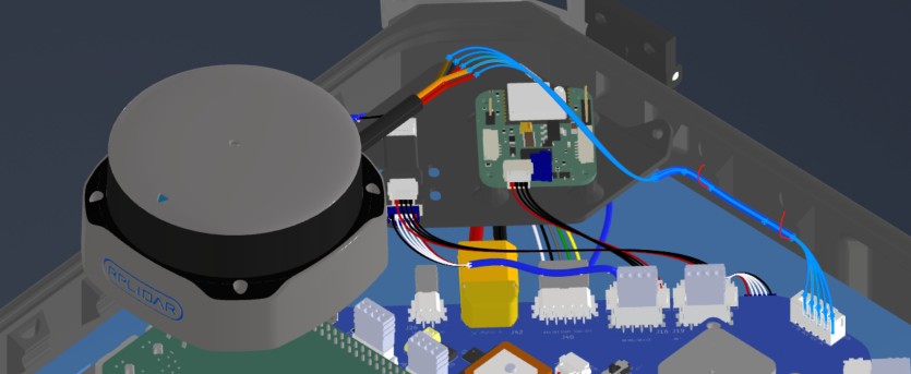
6. Installation & Routing (Vehicle Integration)
Instructions for the technician installing this harness into the chassis.
- Source Connection: Main PCB, U5
- Destination Connection: S2L Lidar
- Routing Path:
- Path - Downward towards connector
- Constraint - N/A
- Fixing - Zip tie in red
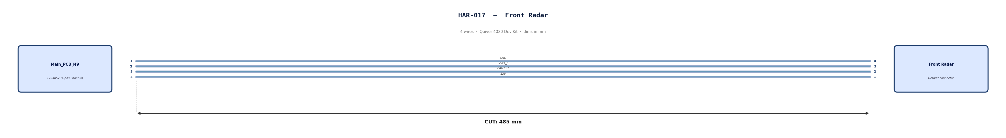
HAR-0017 Front Radar
| FROM | TO |
|---|---|
| Main_PCB J49 | Front Radar |
1. Nailboard
2. Bill of Materials (Kitting)
Gather these parts before starting the build.
| Item Type | Part Number | Description / Spec | Qty Needed |
|---|---|---|---|
| Connector A | 1704857 | 4-Pos Phoenix | 1 |
| Terminals A | Wire | Bare wire, twisted end | 4 |
| Wire | Default | Silicon | 190mm |
| Sleeving | Optional | Mesh | xx mm |
3. Wire Prep (Cut & Strip)
Prepare all wires before assembly.
| Wire ID | Color | Gauge | Cut Length | Strip A | Strip B |
|---|---|---|---|---|---|
| W1 | Default | Default | 485 mm | 6mm | N/A |
| W2 | Default | Default | 485 mm | 6mm | N/A |
| W3 | Default | Default | 485 mm | 6mm | N/A |
| W4 | Default | Default | 485 mm | 6mm | N/A |
4. Termination & Pinout Map
Connect End A to End B following this chart.
| Wire ID | Color | From: 1704857 | To: NRA 15 | Function / Signal |
|---|---|---|---|---|
| W1 | Default | Pin 1 | 4 | GND |
| W2 | Default | Pin 2 | 3 | CAN1_L |
| W3 | Default | Pin 3 | 2 | CAN1_H |
| W4 | Default | Pin 4 | 1 | 12V |
5. Assembly Instructions
- Prep: Cut wires to length and strip insulation per Section 3.
- Populate A: Insert contacts into Connector A housing. Verify "Click" and perform pull-back test.
6. Installation & Routing (Vehicle Integration)
Instructions for the technician installing this harness into the chassis.
- Source Connection: Main PCB, J49
- Destination Connection: Front Radar
- Routing Path:
- Path - Right side top plate entry to bottom plate
- Constraint - other cables
- Fixing - Zip tie in red
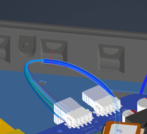
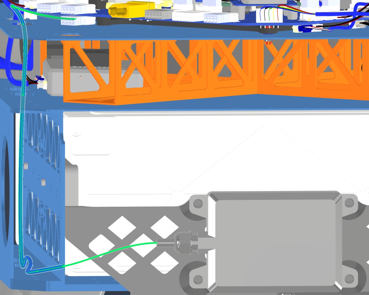
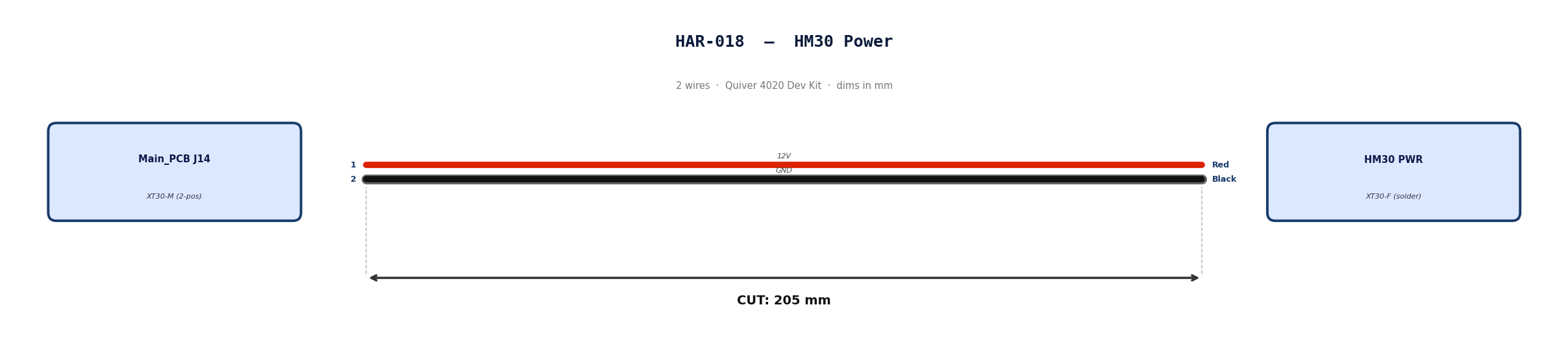
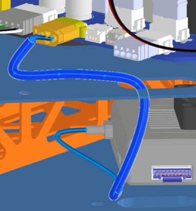
HAR-0018 HM30 Power
| FROM | TO |
|---|---|
| Main_PCB J14 | HM30 PWR |
1. Nailboard
2. Bill of Materials (Kitting)
Gather these parts before starting the build.
| Item Type | Part Number | Description / Spec | Qty Needed |
|---|---|---|---|
| Connector A | XT30-M | 2-Pos XT-30 | 1 |
| Terminals A | Wire | Solder | 2 |
| Wire | 16 AWG | Silicon | 170mm |
| Sleeving | Optional | Mesh | xx mm |
3. Wire Prep (Cut & Strip)
Prepare all wires before assembly.
| Wire ID | Color | Gauge | Cut Length | Strip A | Strip B | |:------- |:----- |:--------- |:--------------- |:------------ | | W1 | Red | Pin 1 | 185 | 10 | | W2 | Black | Pin 2 | 185 | 10 |
4. Termination & Pinout Map
Connect End A to End B following this chart.
| Wire ID | Color | From: 1704857 | To: Spade | Function / Signal |
|---|---|---|---|---|
| W1 | Red | Pin 1 | 1 | 12V |
| W2 | Red | Pin 2 | 2 | GND |
5. Assembly Instructions
- Prep: Cut wires to length and strip insulation per Section 3.
- Solder Side A: Solder cables into housing.
6. Installation & Routing (Vehicle Integration)
Instructions for the technician installing this harness into the chassis.
- Source Connection: Main_PCB, J27
- Destination Connection: ESC 1 PWR
- Routing Path:
- Path - Right side top plate opening
- Constraint - N/A
- Fixing - N/A
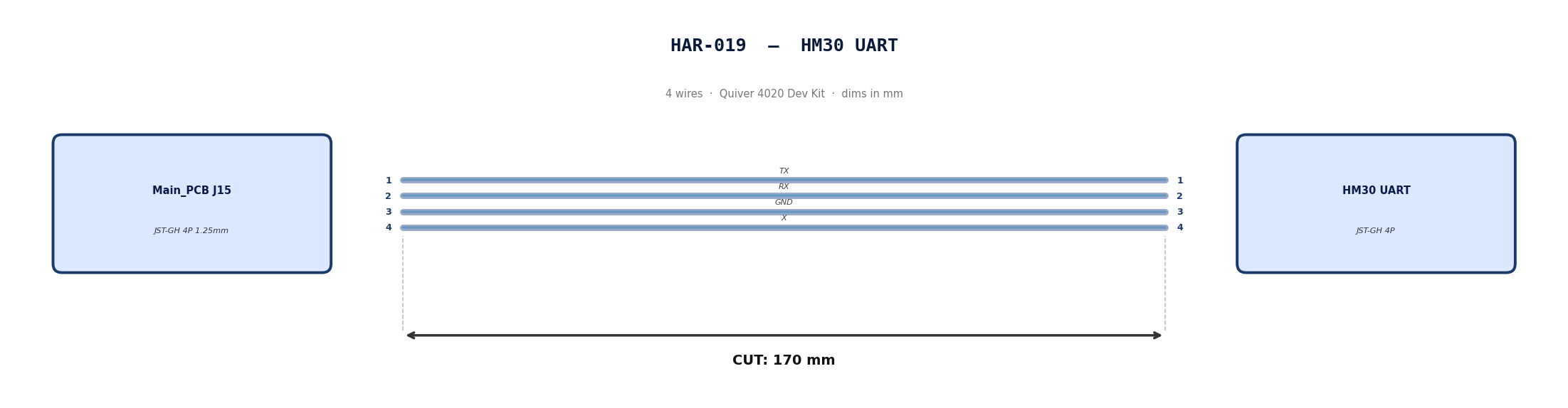
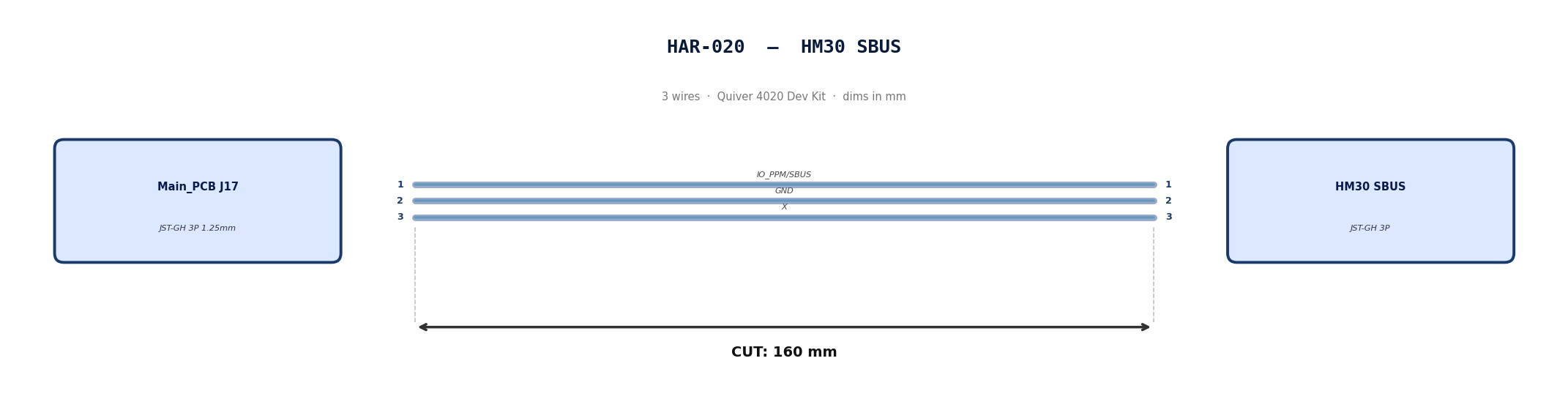
HAR-0019 -> HAR-0020 HM30 Signal
| FROM | TO |
|---|---|
| Main_PCB J15 | HM30 UART |
| Main_PCB J17 | HM30 SBUS |
1. Nailboard
2. Bill of Materials (Kitting)
Gather these parts before starting the build.
| Item Type | Part Number | Description / Spec | Qty Needed |
|---|---|---|---|
| 4 Pin JST Cable | N/A | JST, GH Connector Housing, 1.25mm Pitch, 4 Way | 1 |
| 3 Pin JST Cable | N/A | JST, GH Connector Housing, 1.25mm Pitch, 3 Way | 1 |
| Sleeving | Optional | Mesh | xx mm |
3. Wire Prep (Cut & Strip)
Prepare all wires before assembly.
Pre-made JST-GH cables. No crimping required — source cables at the required lengths below.
| Harness | Connector | Required Length (mm) |
|---|---|---|
| HAR-019 (HM30 UART) | JST-GH 4P | 170 |
| HAR-020 (HM30 SBUS) | JST-GH 3P | 160 |
4. Termination & Pinout Map
Connect End A to End B following this chart.
| Wire ID | Color | From: J15 | To: HM30 UART | Function / Signal |
|---|---|---|---|---|
| W1 | Default | Pin 1 | 1 | TX |
| W2 | Default | Pin 2 | 2 | RX |
| W1 | Default | Pin 1 | 3 | GND |
| W2 | Default | Pin 2 | 4 | X |
| Wire ID | Color | From: J17 | To: HM30 SBUS | Function / Signal |
|---|---|---|---|---|
| W1 | Default | Pin 1 | 1 | IO_PPM_INPUT_AND_SBUS_INPUT |
| W2 | Default | Pin 2 | 2 | GND |
| W1 | Default | Pin 1 | 3 | x |
5. Assembly Instructions
N/A
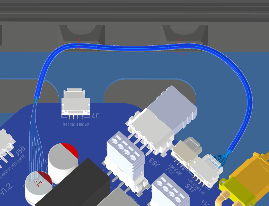
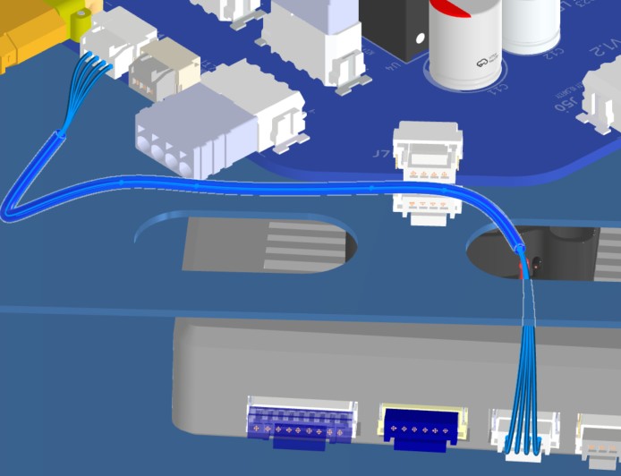
6. Installation & Routing (Vehicle Integration)
Instructions for the technician installing this harness into the chassis.
- Source Connection: Bat_PCB J15, J17
- Destination Connection: HM30
- Routing Path:
- Path - Right side top plate opening
- Constraint - other cables
- Fixing - Zip ties
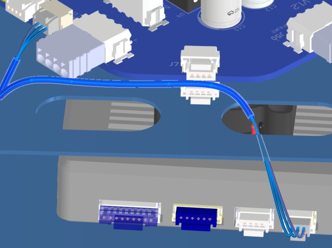
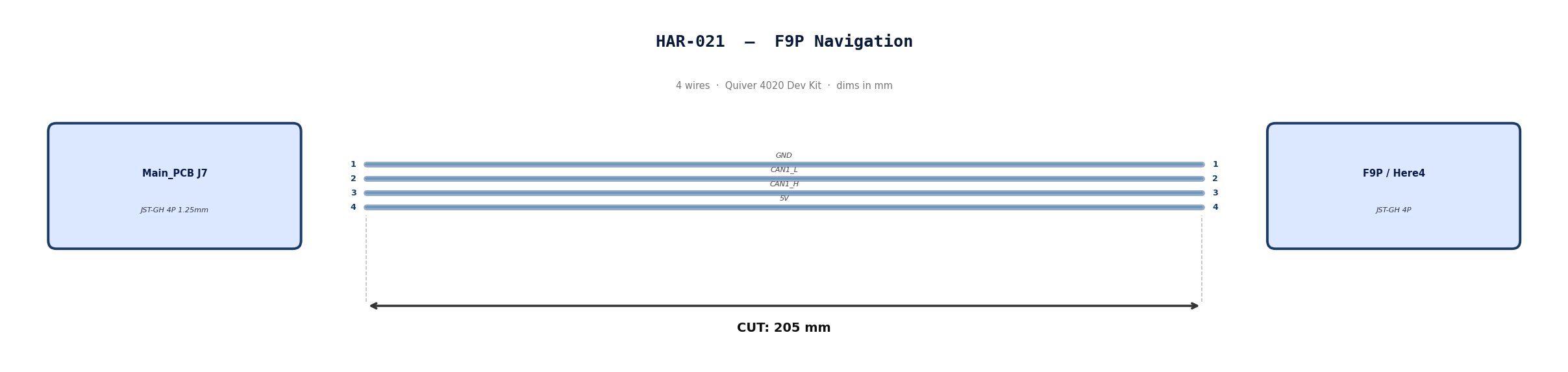
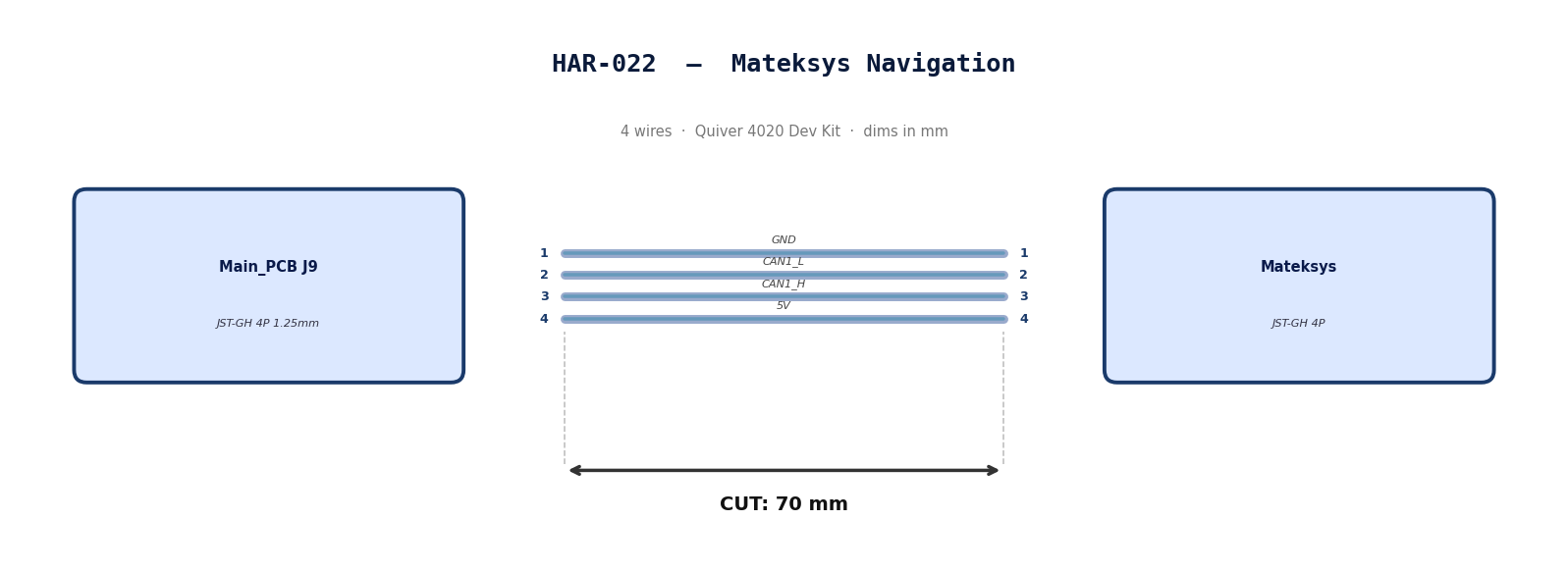
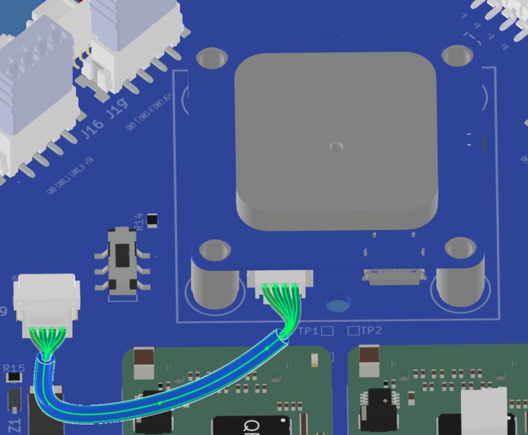
HAR-0021 -> HAR-0022 Navigation
| FROM | TO |
|---|---|
| Main_PCB J7 | F9P |
| Main_PCB J9 | Mateksys |
1. Nailboard
2. Bill of Materials (Kitting)
Gather these parts before starting the build.
| Item Type | Part Number | Description / Spec | Qty Needed |
|---|---|---|---|
| 4 Pin JST Cable | N/A | JST, GH Connector Housing, 1.25mm Pitch, 4 Way | 2 |
| Sleeving | Optional | Mesh | xx mm |
3. Wire Prep (Cut & Strip)
Prepare all wires before assembly.
Pre-made JST-GH cables. No crimping required — source cables at the required lengths below.
| Harness | Connector | Required Length |
|---|---|---|
| HAR-021 (F9P / Here4) | JST-GH 4P | 205mm |
| HAR-022 (Mateksys) | JST-GH 4P | 70mm |
4. Termination & Pinout Map
Connect End A to End B following this chart.
| Wire ID | Color | From: J9 | To: M9N | Function / Signal |
|---|---|---|---|---|
| W1 | Default | Pin 1 | 1 | GND |
| W2 | Default | Pin 2 | 2 | CAN1_L |
| W3 | Default | Pin 1 | 3 | CAN1_H |
| W4 | Default | Pin 2 | 4 | 5V |
| Wire ID | Color | From: J7 | To: F9P | Function / Signal |
|---|---|---|---|---|
| W1 | Default | Pin 1 | 1 | GND |
| W2 | Default | Pin 2 | 2 | CAN1_L |
| W3 | Default | Pin 1 | 3 | CAN1_H |
| W4 | Default | Pin 2 | 4 | 5V |
5. Assembly Instructions
N/A
6. Installation & Routing (Vehicle Integration)
Instructions for the technician installing this harness into the chassis.
-
Source Connection: Main_PCB J7, J9
-
Destination Connection: F9P/Here 4, Mateksys
-
Routing Path:
- Path - Immediately to the right
- Constraint - N/A
- Fixing - N/A
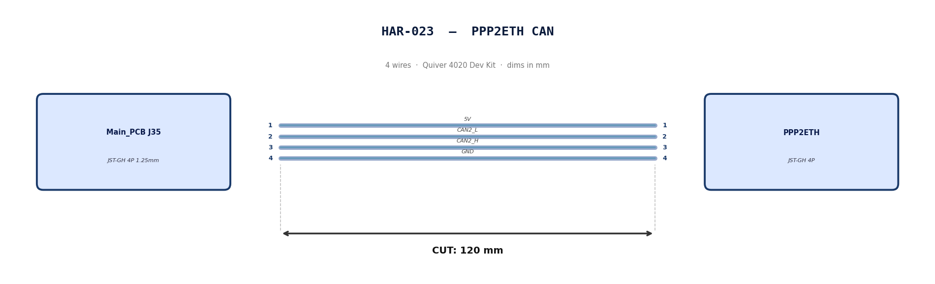
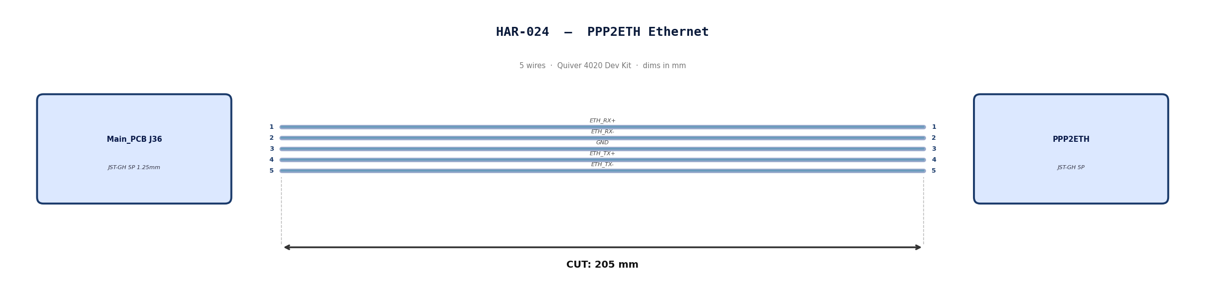
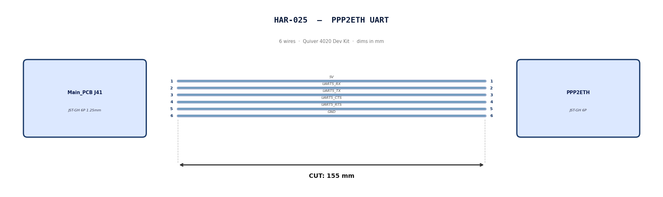
HAR-0023 -> HAR-0025 PPP2ETH
| FROM | TO |
|---|---|
| Main_PCB J35 | PPP2ETH |
| Main_PCB J36 | PPP2ETH |
| Main_PCB J41 | PPP2ETH |
1. Nailboard
2. Bill of Materials (Kitting)
Gather these parts before starting the build.
| Item Type | Part Number | Description / Spec | Qty Needed |
|---|---|---|---|
| 4 Pin JST Cable | N/A | JST, GH Connector Housing, 1.25mm Pitch, 4 Way | 1 |
| 5 Pin JST Cable | N/A | JST, GH Connector Housing, 1.25mm Pitch, 5 Way | 1 |
| 6 Pin JST Cable | N/A | JST, GH Connector Housing, 1.25mm Pitch, 6 Way | 1 |
| Sleeving | Optional | Mesh | xx mm |
3. Wire Prep (Cut & Strip)
Prepare all wires before assembly.
Pre-made JST-GH cables. No crimping required — source cables at the required lengths below.
| Harness | Connector | Required Length |
|---|---|---|
| HAR-023 (PPP2ETH CAN) | JST-GH 4P | 120mm |
| HAR-024 (PPP2ETH Ethernet) | JST-GH 5P | 205mm |
| HAR-025 (PPP2ETH UART) | JST-GH 6P | 155mm |
4. Termination & Pinout Map
Connect End A to End B following this chart.
| Wire ID | Color | From: J35 | To: PPP2ETH | Function / Signal |
|---|---|---|---|---|
| W1 | Default | Pin 1 | 1 | 5V |
| W2 | Default | Pin 2 | 2 | CAN2_L |
| W3 | Default | Pin 3 | 3 | CAN2_H |
| W4 | Default | Pin 4 | 4 | GND |
| Wire ID | Color | From: J7 | To: PPP2ETH | Function / Signal |
|---|---|---|---|---|
| W1 | Default | Pin 1 | 1 | ETH_RX+ |
| W2 | Default | Pin 2 | 2 | ETH_RX- |
| W3 | Default | Pin 3 | 3 | GND |
| W4 | Default | Pin 4 | 4 | ETH_TX+ |
| W5 | Default | Pin 5 | 5 | ETH_TX- |
| Wire ID | Color | From: J7 | To: PPP2ETH | Function / Signal |
|---|---|---|---|---|
| W1 | Default | Pin 1 | 1 | 5V |
| W2 | Default | Pin 2 | 2 | UART5_RX_TEL2 |
| W3 | Default | Pin 3 | 3 | UART5_TX_TEL2 |
| W4 | Default | Pin 4 | 4 | UART5_CTS_TEL2 |
| W5 | Default | Pin 5 | 5 | UART5_RTS_TEL2 |
| W6 | Default | Pin 6 | 6 | GND |
5. Assembly Instructions
N/A
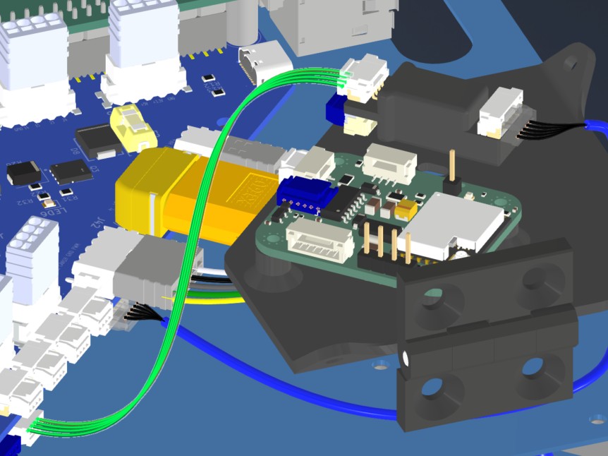
6. Installation & Routing (Vehicle Integration)
Instructions for the technician installing this harness into the chassis.
- Source Connection: Main_PCB J35, J36, J41
- Destination Connection: PPP2ETH
- Routing Path:
- Path - Direct connections. HAR024 will be routed under PPP, Beacon mounting board
- Constraint - PPP,Beacon mounting board
- Fixing - zip tie in red (HAR024)
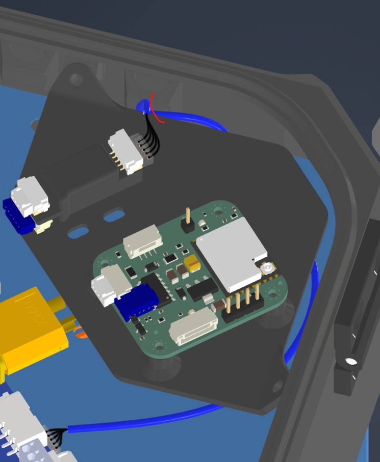
HAR-0026 Remote ID
| FROM | TO |
|---|---|
| Main_PCB J20 | Remote ID CAN |
1. Nailboard
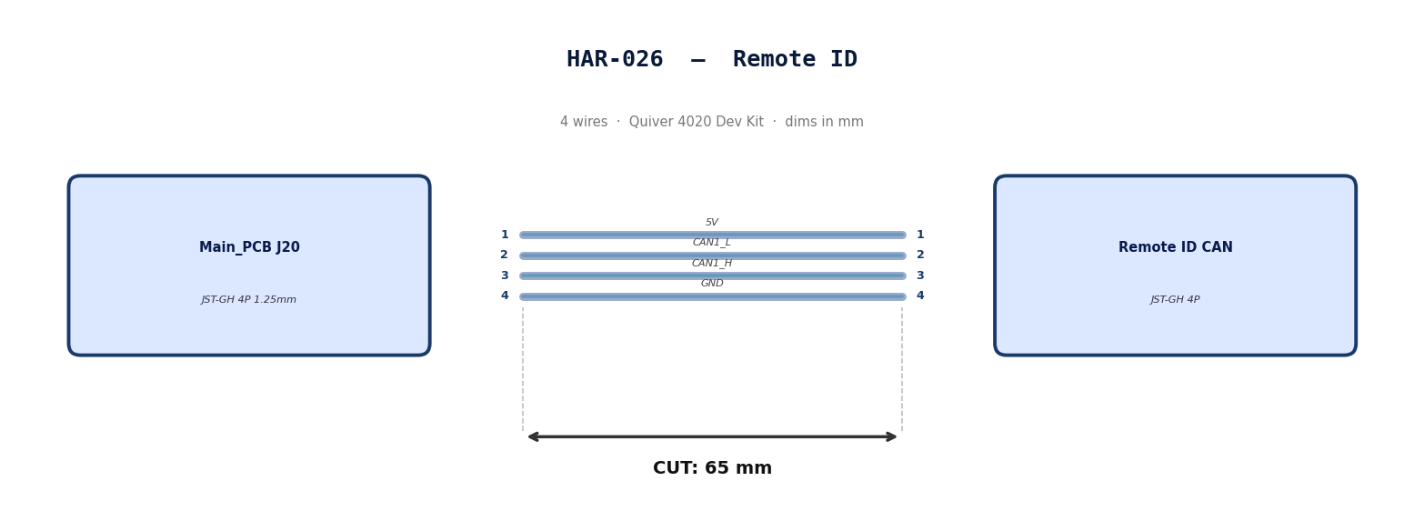
2. Bill of Materials (Kitting)
Gather these parts before starting the build.
| Item Type | Part Number | Description / Spec | Qty Needed |
|---|---|---|---|
| 4 Pin JST Cable | N/A | JST, GH Connector Housing, 1.25mm Pitch, 4 Way | 1 |
| Sleeving | Optional | Mesh | xx mm |
3. Wire Prep (Cut & Strip)
Prepare all wires before assembly.
Pre-made JST-GH cable. No crimping required — source cable at the required length below.
| Harness | Connector | Required Length |
|---|---|---|
| HAR-026 (Remote ID) | JST-GH 4P | 65mm |
4. Termination & Pinout Map
Connect End A to End B following this chart.
| Wire ID | Color | From: J20 | To: RID | Function / Signal |
|---|---|---|---|---|
| W1 | Default | Pin 1 | 1 | 5V |
| W2 | Default | Pin 2 | 2 | CAN1_L |
| W3 | Default | Pin 3 | 3 | CAN1_H |
| W4 | Default | Pin 4 | 4 | GND |
5. Assembly Instructions
N/A
6. Installation & Routing (Vehicle Integration)
Instructions for the technician installing this harness into the chassis.
- Source Connection: Main_PCB J20
- Destination Connection: RID
- Routing Path:
- Path - Direct connection
- Constraint - N/A
- Fixing - N/A
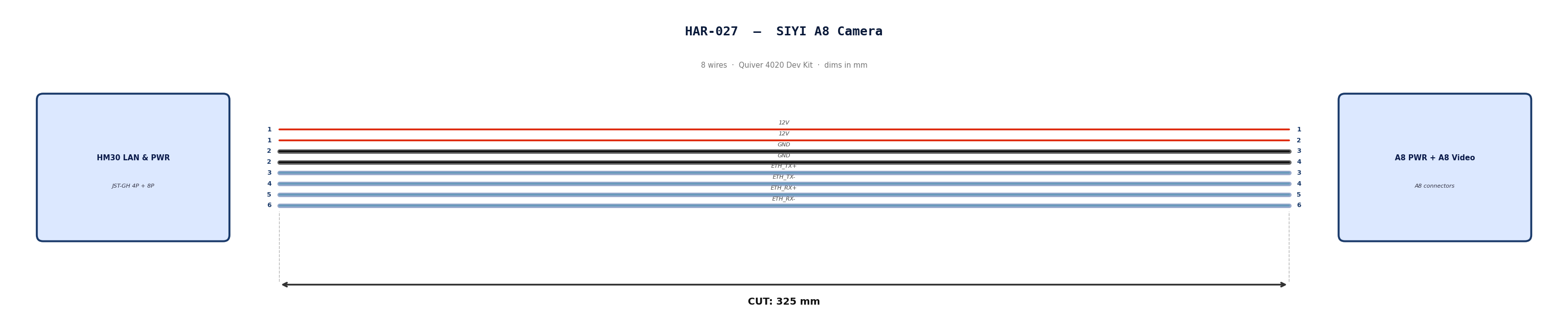
HAR-0027 SIYI Camera
| FROM | TO |
|---|---|
| HM30 LAN & PWR | A8 PWR |
| HM30 LAN & PWR | A8 Video & Protocol |
1. Nailboard
2. Bill of Materials (Kitting)
Gather these parts before starting the build.
| Item Type | Part Number | Description / Spec | Qty Needed |
|---|---|---|---|
| 4 Pin JST Cable | N/A | JST, GH Connector Housing, 1.25mm Pitch, 4 Way | 1 |
| 8 Pin JST Cable | N/A | JST, GH Connector Housing, 1.25mm Pitch, 6 Way | 1 |
| Sleeving | Optional | Mesh | xx mm |
3. Wire Prep (Cut & Strip)
Prepare all wires before assembly.
Pre-made JST-GH cables. No crimping required — source cables at the required lengths below.
| Harness | Connector | Required Length |
|---|---|---|
| HAR-027 power (4P) | JST-GH 4P | 325mm |
| HAR-027 video (8P) | JST-GH 8P | 325mm |
4. Termination & Pinout Map
Connect End A to End B following this chart.
| Wire ID | Color | From: HM30 LAN & PWR | To: A8 PWR | Function / Signal |
|---|---|---|---|---|
| W1 | Default | Pin 1 | 1 | 12V |
| W2 | Default | Pin 1 | 2 | 12V |
| W3 | Default | Pin 2 | 3 | GND |
| W4 | Default | Pin 2 | 4 | GND |
| Wire ID | Color | From: HM30 LAN & PWR | To: A8 Vid | Function / Signal |
|---|---|---|---|---|
| W1 | Default | Pin 3 | 3 | ETH_TX+ |
| W2 | Default | Pin 4 | 4 | ETH_TX- |
| W3 | Default | Pin 5 | 5 | ETH_RX+ |
| W4 | Default | Pin 6 | 6 | ETH_RX- |
5. Assembly Instructions
N/A
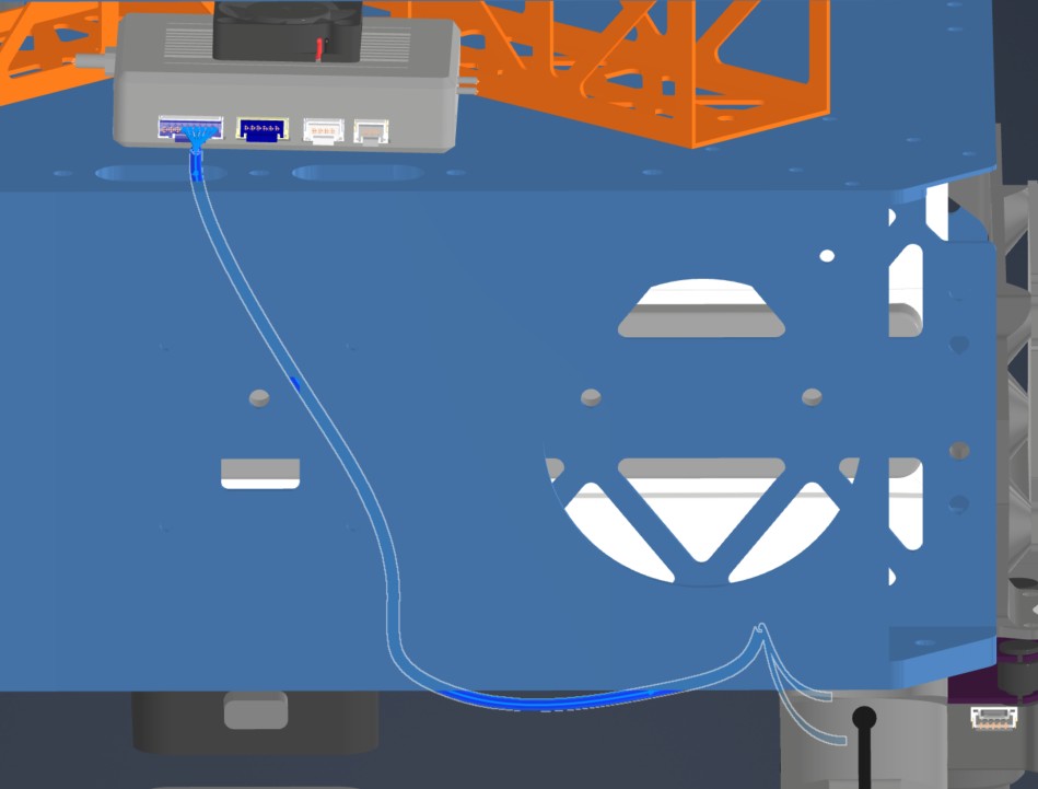
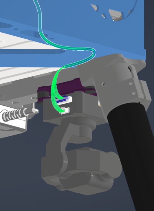
6. Installation & Routing (Vehicle Integration)
Instructions for the technician installing this harness into the chassis.
- Source Connection: HM30 LAN & PWR
- Destination Connection: SIYI A8
- Routing Path:
- Path - Right side middle plate opening to underside of bottom plate
- Constraint - Other cables
- Fixing - Undecided zip ties
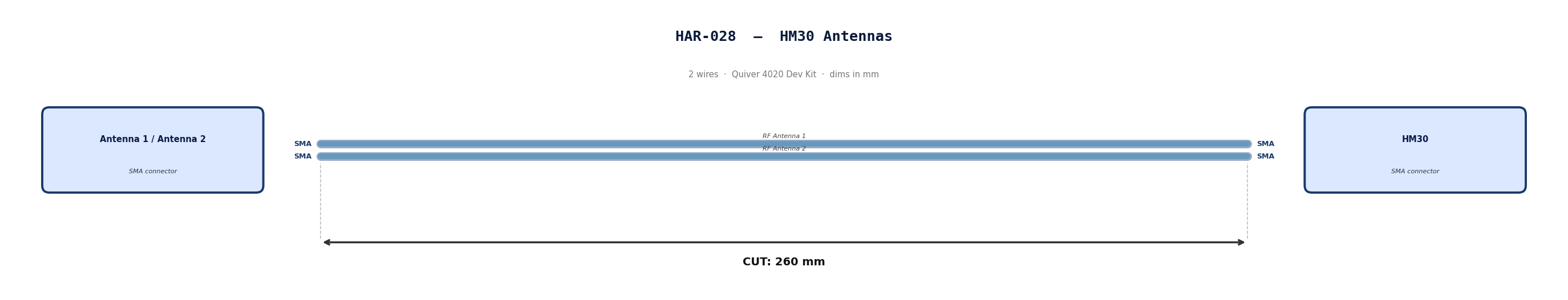
HAR-0028 Antenna
| FROM | TO |
|---|---|
| Antenna 1 | HM30 |
| Antenna 2 | HM30 |
1. Nailboard
2. Bill of Materials (Kitting)
Gather these parts before starting the build.
Pre made cables with SMA connector. Length adjustment not required.
3. Wire Prep (Cut & Strip)
N/A
4. Termination & Pinout Map
N/A
5. Assembly Instructions
N/A
6. Installation & Routing (Vehicle Integration)
Instructions for the technician installing this harness into the chassis.
- Source Connection: Antenna
- Destination Connection: HM30
- Routing Path:
- Path - Through enclosure provisions to middle plate
- Constraint - N/A
- Fixing - N/A
General Assembly
BOM for the Assembly
Table 1. Structure Parts
| ID | Part Name | Material | Sourcing | Quantity |
|---|---|---|---|---|
| 1111 | Upper plate | Aluminum | Laser Cut | 1 |
| 1112 | Middle plate | Aluminum | Laser Cut | 1 |
| 1113 | Lower plate | Aluminum | Laser Cut | 1 |
| 1211 | Cockpit Support Beam CW Long | Aluminum | Laser Cut | 1 |
| 121X | Cockpit Support Beam CCW Back | Aluminum | Laser Cut | 2 |
| 122X | Battery Wall | Aluminum | Laser Cut | 2 |
| 131X | Landing Gear Vertical Tubes | Carbon-Fiber | Cut-to-Length | 4 |
| 132X | Landing Gear Horizontal Tubes | Carbon-Fiber | Cut-to-Length | 2 |
| 133X | Landing Gear Main Adapters | Aluminum | Off-the-Shelf | 4 |
| 134X | Landing Gear Tube Joints | Aluminum | Off-the-Shelf | 4 |
| 135X | Landing Gear Foam Wrap | Foam | Off-the-Shelf | 4 |
| 14X1 | Foldable Motor Arm Connectors | Aluminum | Off-the-Shelf | 4 |
| 14X2 | Motor Arm Tubes | Carbon-Fiber | Cut-to-Length | 4 |
| 21X2 | Attachment Interface | Aluminum | Off-the-Shelf | 3 |
| 21X1 | Attachment Interface Spacer Left & Right | PETG-CF | 3D Print | 2 |
| 2131 | Attachment Interface Spacer Bottom | PETG-CF | 3D Print | 1 |
| 221X | Battery sliders | PETG-CF | 3D Print | 2 |
| 2311 | Main PCB Mount | PETG-CF | 3D Print | 1 |
| 2312 | BC PCB Mount | PETG-CF | 3D Print | 1 |
| 2313 | BC PCB Cover | PETG-CF | 3D Print | 1 |
| 2321 | Sensor Mount | PETG-CF | 3D Print | 1 |
| 2331 | GNSS Mount | PETG-CF | 3D Print | 1 |
| 2341 | PPP Adapter & Beacon Mount | PETG-CF | 3D Print | 1 |
| 2411 | Main Enclosure | PETG-CF | 3D Print | 1 |
| 2412 | Enclosure Top Cap | PETG-CF | 3D Print | 1 |
| 242X | Enclosure Hinge | Zinc | Off-the-Shelf | 2 |
| 243X | Enclosure Latch | Steel | Off-the-Shelf | 2 |
Table 2. Fasteners
| Fastener ID | Fastener Description | Quantity | Reference Part |
|---|---|---|---|
| Rivet 1 | 4mm Diameter for 1 mm - 2.5 mm thickness | 26 | 97525A224 |
| Rivet 2 | 4mm Diameter for 2.5 mm - 4.5 mm thickness | 10 | 97525A251 |
| Rivet 3 | 4mm Diameter for 4.5 mm - 6.4 mm thickness | 10 | 97525A226 |
| Screw 1 | Socket Head Screw M3x10 | 8 | 91292A113 |
| Screw 2 | Flanged Button Head Screw M4x10 | 16 | 92095A190 |
| Screw 4 | Socket Head Screw M3x12 | 8 | 91292A114 |
| Screw 5 | Socket Head Screw M3x8 | 75 | 91292A112 |
| Screw 6 | Socket Head Screw M3x40 | 16 | 91292A024 |
| Screw 7 | Hex Drive Flat Head Screw M3x8 | 4 | 92125A128 |
| Screw 8 | Hex Drive Flat Head Screw M3x10 | 8 | 92125A130 |
| Screw 9 | Socket Head Screw M4x8 | 8 | 91292A108 |
| Screw 10 | Socket Head Screw M2x6 | 4 | 91292A832 |
| Screw 11 | Flanged Button Head Hex-Drive Screw M3x6 | 27 | 97654A674 |
| Screw 12 | Socket Head Hex-Drive Screw M2x5 | 4 | 92855A837 |
| Screw 13 | Socket Head Hex-Drive Screw M2.5x8 | 4 | 91292A012 |
| Screw 14 | Socket Head Hex-Drive Screw M2x10 | 4 | 91292A833 |
| Screw 15 | Socket Head Hex-Drive Screw M5x8 | 4 | 91292A191 |
| Screw 16 | Button Head Hex Drive Screw M3x40 | 4 | 92095A203 |
| Screw 17 | Socket Head Screw M3x6 | 8 | 90751A110 |
| Screw 3 | Button Head Hex-Drive Screw M2x4 | 12 | 92095A451 |
| Insert 1 | M3 Threaded Inserts - 5.7 mm | 50 | 94459A140 |
| Insert 2 | M4 Threaded Inserts | 8 | 94180A351 |
| Insert 3 | M2 Threaded Inserts | 4 | 94180A312 |
| Insert 4 | M3 Threaded Inserts - 3.8 mm | 16 | 94180A331 |
| Washer 1 | M3 General Purpose Washer 3.2 mm ID, 6 mm OD | 123 | 98689A112 |
| Washer 2 | M4 General Purpose Washer 4.3 mm ID, 9 mm OD | 8 | 93475A230 |
| Washer 3 | M2 Nylon Washer 2.2 mm ID, 5 mm OD | 12 | 95610A110 |
| Washer 4 | M2.5 Nylon Washer 2.7 mm ID, 5.6 mm OD | 4 | 95610A011 |
| Washer 5 | M3 Nylon Washer 3.2 mm ID, 6 mm OD | 4 | 95610A704 |
| Washer 6 | M5 General Purpose Washer 5.3 mm ID, 10 mm OD | 4 | 93475A240 |
| Nut 1 | Nylon-Insert Locknut M3 | 16 | 90576A811 |
| Vibration Mount | M3 Rubber Anti-Vibration Spacer | 5 | Amazon |
| Grommet 1 | Circular Grommet OD: 20 mm | 4 | Amazon |
| Grommet 2 | Oval Grommet 27x13 mm | 12 | Amazon |
| Silicone Foam Seal Strip | Circular, OD: 8 mm | 1 | Amazon |
Table 3. Tools and Consumables
| Item | Description | Reference |
|---|---|---|
| Allen key set | Metric, M2 - M5 | |
| Wrench set | Metric | |
| Cordless screwdriver or drill press | ||
| Riveting tool | For 4 mm rivets | |
| Double-Sided Tape | Heavy Duty | |
| Loctite Threadlocker Purple 222 | Low-strength threadlocker | McMaster-Carr 1810A28 |
| Loctite Threadlocker Blue 242 | Medium-strength threadlocker | McMaster-Carr 91458A113 |
| Loctite Threadlocker Red 262 | High-strength threadlocker | McMaster-Carr 91458A170 |
| Würth Super RTV Silicone Black | 200 ml, black RTV silicone | Model Number: 08933311 |
| Bambulab PETG-CF Filament | PETG-CF Filament | Bambulab US Store |
Preparation
1111, 1112 & 1113 - Rack Plates
- All three are aluminum 6 series sheets, laser cut, sanded.
- Bounding box dimension is 300x300 mm for each.
- Qty: 1 each.
- Reference supplier: Rapiddirect
| 1111 (Upper Plate) | 1112 (Mid Plate) | 1113 (Lower Plate) | |
|---|---|---|---|
| Thickness | 1 mm | 1 mm | 4 mm |
| Image |  |  |  |
| CAD File | 1111 | 1112 | 1113 |
1211, 1212 & 1213 - Cockpit Support Beams
- All three are aluminum 6 series, 40x40x1 mm square tubes, laser cut, sanded.
- Part 1211; Qty: 1.
- Parts 1212 and 1213 are identical; Qty: 2.
- Reference supplier: Rapiddirect
| 1211 (Cockpit Support Beam CW Long) | 1212 & 1213 (Cockpit Support Beam CCW Back & Front) | |
|---|---|---|
| Length | 289.2 mm | 124.2 mm |
| Image |  |  |
| CAD File | 1211 | 1212 & 1213 |
1221 & 1222 - Battery Walls
- Both are aluminum 6 series, 1000x30x2 mm rectangular tubes, laser cut, sanded.
- Length is 300 mm for each.
- Parts are identical; Qty: 2.
- Reference supplier: Rapiddirect
| 1221 & 1222 (Battery Wall Left & Right) | |
|---|---|
| Image |  |
| CAD File | 1221 & 1222 |
1311, 1312, 1313 & 1314 - Landing Gear Vertical Tubes
- Carbon-fiber tubes, 30 mm diameter, 1 mm thickness.
- Length is 400 mm for each.
- Parts are identical; Qty: 4.
- Note: Order parts pre-cut to the specified length if available; otherwise, cut to length.
1321 & 1322 - Landing Gear Horizontal Tubes
- Carbon-fiber tubes, 30 mm diameter, 1 mm thickness.
- Length is 500 mm for each.
- Parts are identical; Qty: 2.
- Note: Order parts pre-cut to the specified length if available; otherwise, cut to length.
1331, 1332, 1333 & 1334 - Landing Gear Main Adapters
- Off-the-shelf component.
- 30 mm option.
- Product Link: Link
- Qty: 4.
[!NOTE]
- This product became available in RJXHobby catalog after a customized order for 30 mm tube diameter.
- If not available in the catalog, contact RJXHobby for the customization.
- Request 30 mm diameter variant of this product with bolt pattern of 30 mm version of this one.
[!Note] If detachable landing gear is not favored, you may use 30 mm version of this product.
| 1331, 1332, 1333 & 1334 (Landing Gear Main Adapter) |
|---|
 |
1341, 1342, 1343 & 1344 - Landing Gear Tube Joints
- Off-the-shelf component.
- Product Link: Link
- Qty: 4.
| 1341, 1342, 1343 & 1344 (Landing Gear Tube Joint) | |
|---|---|
| Image |  |
1351, 1352, 1353 & 1354 - Landing Gear Foam Wraps.
- Pipe insulation foam, 28 mm inner diameter, 46 mm outer diameter.
- Length is 103 mm each.
- Parts are identical; Qty: 4.
- Cut from stock material to length.
- Product Link: Link
| 1351, 1352, 1353 & 1354 (Landing Gear Foam Wrap) |
|---|
 |
1411, 1421, 1431 & 1441 - Motor Arm Foldable Connectors
- 30 mm tube diameter version.
- Parts are identical; Qty: 4.
- Product Link: Link
| 1411, 1421, 1431 & 1441 (Motor Arm Foldable Connectors) |
|---|
 |
1412, 1422, 1432 & 1442 - Motor Arms
- Carbon-fiber tubes, 30 mm diameter, 1 mm thickness.
- Length is 360 mm for each.
- Parts are identical; Qty: 4.
- Note: Order parts pre-cut to the specified length if available; otherwise, cut to length.
2111, 2121 & 2131 - Attachment Interface Spacers
- 3D printed.
- PETG-CF.
- Use 6 wall loops.
- Parts 2111 and 2121 are identical; Qty: 2.
- Part 2131; Qty: 1.
| 2111 & 2121 (Attachment Interface Spacers, Left and Right) | 2131 (Attachment Interface Spacer, Bottom) | |
|---|---|---|
| Image |  |  |
| CAD File | 2111 & 2121 | 2131 |
2112, 2122 & 2132 - Attachment Interfaces
- Parts are identical, order 3 parts.
- Select "Without PCB Board" option.
- Product Link: Link
| 2112, 2122 & 2132 (Attachment Interface) |
|---|
 |
2211 & 2212 - Battery Sliders
- 3D printed.
- PETG-CF.
- Use 6 wall loops.
- Parts are identical; Qty: 2.
| 2211 & 2212 (Battery Slider) | |
|---|---|
| Image |  |
| CAD File | 2211 & 2212 |
2311 - Main PCB Mount
- 3D printed.
- PETG-CF.
- Use 6 wall loops.
- Qty: 1.
| 2311 (Main PCB Mount) | |
|---|---|
| Image |  |
| CAD File | 2311 |
2312 - Battery Connector PCB Mount
- 3D printed.
- PETG-CF.
- Use 6 wall loops.
- Qty: 1.
| 2312 (BC PCB Mount) | |
|---|---|
| Image |  |
| CAD File | 2312 |
2313 - Battery Connector PCB Cover
- 3D printed.
- PETG-CF.
- Use 6 wall loops.
- Qty: 1.
| 2313 (BC PCB Cover) | |
|---|---|
| Image |  |
| CAD File | 2313 |
2321 - Sensor Mount
- 3D printed.
- PETG-CF.
- Use 6 wall loops.
- Qty: 1.
| 2321 (Sensor Mount) | |
|---|---|
| Image |  |
| CAD File | 2321 |
2331 - GNSS Mount
- 3D printed.
- PETG-CF.
- Use 6 wall loops.
- Qty: 1.
| 2331 (GNSS Mount) | |
|---|---|
| Image |  |
| CAD File | 2331 |
2341 - PPP & Beacon Mount
- 3D printed.
- PETG-CF.
- Use 6 wall loops.
- Qty: 1.
| 2341 (PPP & Beacon Mount) | |
|---|---|
| Image |  |
| CAD File | 2341 |
2411 - Main Enclosure
- 3D printed.
- PETG-CF.
- Use 6 wall loops.
- Qty: 1.
| 2411 (Main Enclosure) | |
|---|---|
| Image |  |
| CAD File | 2411 |
2412 - Top Cap
- 3D printed.
- PETG-CF.
- Use 6 wall loops.
- Mind the print orientation as shown.
- Qty: 1.
| 2412 (Top Cap) | |
|---|---|
| Image |  |
| Print Orientation |  |
| CAD File | 2412 |
2421 & 2422 - Enclosure Hinges
- Off-the-shelf component.
- Part Number: GN 237-ZD-30-30-A-SW
- Product Link: Link
- Qty: 2.
| 2421 & 2422 (Enclosure Hinges) |
|---|
 |
2431 & 2432 - Enclosure Latches
- Off-the-shelf component.
- Screw on draw latch.
- Parts are identical; Qty: 2.
- Product Link:
- US: Link
- UK: Latch and catch plate are sold separately.
3322 & 3323 - Busbars
- Both are Copper C110 | CU ETP, laser cut, bent.
- Bounding box dimension is 300x300 mm for each.
- Qty: 1 each.
- Reference supplier: Rapiddirect
| 3322 (Busbar Positive) | 3323 (Busbar Negative) | |
|---|---|---|
| Image |  |  |
| CAD File | 3322 | 3323 |
| -- |
3324 - BC PCB Heatsink
- Aluminum 6 series, laser cut, sanded.
- Experimental part:
- Order both 4 mm and 5 mm thickness variants for evaluation.
- Qty: 1 each.
- Reference supplier: Rapiddirect
| 3324 (BC PCB Heatsink) | |
|---|---|
| Image |  |
| CAD File | 3324 - 4 mm , 3324 - 5 mm |
Assembly Steps
Step 1. Assemble the Cockpit Support Beams on Mid Plate
-
Parts needed:
- 1112 (Mid Plate)
- 1211, 1212 & 1213 (Cockpit Support Beams)
- Rivet 1 x13 (4mm Diameter for 1 mm - 2.5 mm thickness)
-
Place the cockpit support beams on the mid plate as shown in the picture.
-
Rivet the cockpit support beams from the mid plate on the holes shown in the picture.
| Orientation | Rivet Holes |
|---|---|
 |  |
Step 2. Install the Battery Walls
- Parts needed:
- 1221 & 1222 (Battery Walls)
- Rivet 2 x10 (4mm Diameter for 2.5 mm - 4.5 mm thickness)
- Place the battery walls on the sides of the chassis as shown in the picture.
- Make sure the dented side stays on the chassis side.
- Rivet the battery walls from the mid plate on the holes shown in the picture.
| Orientation | Rivet Holes |
|---|---|
 |  |
Step 3. Install the Motor Arm Connectors
-
Parts needed:
- 14X1 x4 (Foldable Motor Arm Connectors)
- Screw 5 x16 (Socket Head Screw M3x8)
- Screw 1 x8 (Socket Head Screw M3x10)
- Washer 1 x24 (M3 General Purpose Washer 3.2 mm ID, 6 mm OD)
- Loctite Threadlocker Blue 242
- Loctite Threadlocker Red 262
-
Remove the fasteners marked in the picture.
- Apply Loctite Threadlocker Red on the fasteners.
- Secure the fasteners back.
| Motor Arm Connector - Loctite Threadlocker Application |
|---|
 |
- Place the motor arm connectors on the chassis as shown in the picture.
- Secure the motor arm connectors on the chassis.
- Use Screw 5 for red holes and Screw 1 for green holes.
- Use Loctite Threadlocker Blue.
- Use Washer 1.
- Use cordless screwdriver where possible, or else an allen key.
| Orientation | Screw Holes |
|---|---|
 |  |
Step 4. Install the Lower Plate
- Parts needed:
- 1113 (Lower Plate)
- Rivet 3 x10 (4mm Diameter for 4.5 mm - 6.4 mm thickness)
- Place the lower plate on the chassis as shown in the picture.
- Rivet the lower plate to the chassis on the holes shown in the picture.
| Orientation | Rivet Holes |
|---|---|
 |  |
Step 5. Install the Upper Plate
-
Parts needed:
- 1111 (Upper Plate)
- Rivet 1 x13 (4mm Diameter for 1 mm - 2.5 mm thickness)
- Screw 5 x24 (Socket Head Screw M3x8)
- Washer 1 x24 (M3 General Purpose Washer 3.2 mm ID, 6 mm OD)
- Loctite Threadlocker Blue 242
-
Place the upper plate over the chassis as shown in the picture.
-
Rivet the cockpit support beams from the upper plate on the holes shown in the picture.
-
Screw the motor arm connectors from the upper plate with Screw 5.
- Use Washer 1.
- Use Loctite Threadlocker Blue.
| Orientation | Rivet Holes |
|---|---|
 |  |
Step 6. Install the Main PCB Mount
-
Parts needed:
- 2311 (Main PCB Mount)
- Screw 11 x5 (Flanged Button Head Hex-Drive Screw M3x6)
- Vibration Mount x5 (M3 Rubber Anti-Vibration Spacer)
- Insert 4 x16 (M3 Threaded Inserts - 3.8 mm)
- Loctite Threadlocker Blue 242
-
Install 11x Insert 4 into the top face of the Main PCB Mount as shown in the picture.
| Top Insert Locations |
|---|
 |
- Install 5x Insert 4 into the bottom face of the Main PCB Mount (2311) as shown in the picture.
| Bottom Insert Locations |
|---|
 |
- Install 5x Vibration Mount into the designated holes on the Upper Plate (1111).
- Orientation: Ensure the longer side of the rubber dampener (3 mm section) is facing upwards, towards where the 3D-printed holder will sit.
| Vibration Mount Locations | Vibration Mount Insertion |
|---|---|
 |  |
- Apply a small amount of Loctite Threadlocker Blue to the threads of the 5x Screw 11 (M3x6) flat head screws.
- Align the 3D-printed mount over the rubber dampeners.
- Insert the Screw 11 (M3x6) screws through the center of the rubber dampeners and thread them into the bottom-side inserts of the PCB holder.
- Compression: Tighten the screws until the rubber dampener is compressed to a height of approximately 2.0 mm. Refer to the visual guide below.
| Vibration Mount Compression |
|---|
 |
Step 7. Install the Battery Connector PCB Mount
-
Parts needed:
- 2312 (BC PCB Mount)
- Insert 1 x10 (M3 Threaded Inserts - 5.7 mm)
- Screw 5 x3 (Socket Head Screw M3x8)
- Washer 1 x3 (M3 General Purpose Washer 3.2 mm ID, 6 mm OD)
-
Place Insert 1 to the holes shown in the picture, on the top and bottom sides of the BC PCB mount.
- Use a soldering iron to place them inside the plastic.
| Top | Bottom |
|---|---|
 |  |
- Place the Battery Connector PCB mount over the mid plate.
- Secure it with 3x Screw 5 in total from below the mid plate on the holes below.
- Use Washer 1 for the holes.
 ---
### Step 8. Install the Battery Sliders
- Parts needed:
- 2211, 2212 (Battery Sliders)
- Insert 2 x8 (M4 Threaded Inserts)
- Screw 9 x8 (Socket Head Screw M4x8)
- Washer 2 x8 (M4 General Purpose Washer 4.3 mm ID, 9 mm OD)
---
### Step 8. Install the Battery Sliders
- Parts needed:
- 2211, 2212 (Battery Sliders)
- Insert 2 x8 (M4 Threaded Inserts)
- Screw 9 x8 (Socket Head Screw M4x8)
- Washer 2 x8 (M4 General Purpose Washer 4.3 mm ID, 9 mm OD)
- Place Insert 2 to the holes shown in the picture on both of the battery slides.
- Use a soldering iron to place them inside the plastic.

- Place the battery sliders inside the battery compartment.
- Be careful about the orientation of the angled end, they should point where the cutouts on the plates are.
- Secure it with 8x Screw 9 in total from the sides of the frame.
- Use Washer 2 with the screws.
| Orientation | Installation Holes |
|---|---|
 |  |
Step 9. Install the Landing Gear
-
Parts needed:
- 131X, 132X (Landing Gear Horizontal & Vertical Tubes)
- 133X (Landing Gear Main Adapters)
- 134X (Landing Gear Tube Joints)
- 135X (Landing Gear Foam)
- Screw 2 x16 (Flanged Button Head Screw M4x10)
- Screw 5 x16 (Socket Head Screw M3x8)
- Washer 1 x16 (M3 General Purpose Washer 3.2 mm ID, 6 mm OD)
- Loctite Threadlocker Blue 242
- Loctite Threadlocker Purple 222
-
Place the landing gear main adapters below the chassis, as shown in the picture.
- The adapters are facing outward, to the left and right of the structure.
- Screw the adapters with 16x Screw 2 to the chassis.
- Use Loctite Threadlocker Blue to secure the screws.
| Orientation | Installation Holes |
|---|---|
 |  |
- Insert the vertical landing gear tubes inside landing gear main adapters.
- Make sure the tubes are inserted all the way.
- Tighten the clamps to secure the tubes in place.
[!NOTE]
Due to the lack of the detachable landing gear adapter geometry, this image depicts the old adapter. It should be updated with a real life image.
| Landing Gear Adapter |
|---|
 |
-
Make sure the chassis stands level on the ground.
- If not, measure and equalize the tube lengths.
-
Assemble landing gear tube joints and the horizontal tubes as shown in the picture.
- Insert the vertical tubes inside the holes before tightening the screws.
- Use Screw 5.
- Use Washer 1.
- Use Loctite Threadlocker Purple.
| Positioning | Correct Final Appearance |
|---|---|
 |  |
[!NOTE]
Due to the lack of the landing gear tee joint geometry, this image depicts the old joint. It should be updated with a real life image.
- Slide the landing gear foams to the end of the horizontal tubes.
Step 10. Install Sensor Mount
-
Parts needed:
- 2321 (Sensor Mount)
- Insert 1 x10 (M3 Threaded Inserts - 5.7 mm)
- Screw 4 x4 (Socket Head Screw M3x12)
- Screw 5 x2 (Socket Head Screw M3x8)
- Washer 1 x6 (M3 General Purpose Washer 3.2 mm ID, 6 mm OD)
- Nut 1 x4 (Nylon-Insert Locknut M3)
- Loctite Threadlocker Purple 222
-
Place Insert 1 to the holes shown in the picture.
- Use a soldering iron to place them inside the plastic.
- 10 in total.
| Insert 1 (5.7 mm) Locations |
|---|
 |
 |
- Secure the sensor mount on the lower plate.
- Screw head stays inside the mount.
- Use Screw 4.
- Use Washer 1 on the nut side.
- Use Nut 1.
- DO NOT use Loctite Threadlocker.
| Lower Plate Fasteners |
|---|
 |
- Secure the sensor mount on the battery walls.
- Use Screw 5.
- Use Washer 1.
- Use Loctite Threadlocker Purple.
| Battery Wall Fasteners |
|---|
 |
Step 11. Insert Grommets
-
Parts needed:
- Grommet 1 x4 (Circular Grommet OD: 20 mm)
- Grommet 2 x12 (Oval Grommet 27x13 mm)
-
Insert 4x Grommet 1 into the holes over the motor arm connectors at each corner.
| Grommet 1 Location |
|---|
 |
- Insert 12x Grommet 2 into the holes on the sides of upper, mid and lower plates on each side.
| Grommet 2 Location |
|---|
 |
Step 12. Install PCBs & Onboard Components
-
Parts needed:
- 2331 (GNSS Mount)
- 3311 (Main PCB)
- 3321 (BC PCB)
- 3331 (FC PCB)
- 3332 (Flight Controller)
- 3312 (RPI 5)
- 3313 x2 (GigaBlox Nano Ethernet Switch)
- 3315 (Mateksys GNSS M9N-G4-3100)
- 3251 (RTK GNSS)
- Screw 4 x4 (Socket Head Screw M3x12)
- Screw 11 x14 (Flanged Button Head Hex-Drive Screw M3x6)
- Screw 12 x4 (Socket Head Hex-Drive Screw M2x5)
- Screw 13 x4 (Socket Head Hex-Drive Screw M2.5x8)
- Screw 14 x4 (Socket Head Hex-Drive Screw M2x10)
- Washer 3 x12 (M2 Nylon Washer 2.2 mm ID, 5 mm OD)
- Washer 4 x4 (M2.5 Nylon Washer 2.7 mm ID, 5.6 mm OD)
- Washer 5 x4 (M3 Nylon Washer 3.2 mm ID, 6 mm OD)
- Loctite Threadlocker Purple 222
- Loctite Threadlocker Blue 242
-
Place the Battery Connector PCB as shown in the picture.
- Apply Thermal Paste to the Heatsink.
- Secure it with 3x Screw 11.
| BC PCB & Bolt Locations |
|---|
 |
- Place the Main PCB as shown in the picture.
- See the warning before installation.
- Secure it with 7x Screw 11.
[!CAUTION] CRITICAL: Trim DC-DC Converter Pins
Before mounting the Main PCB, the through-hole pins of the DC-DC converters must be trimmed on the underside of the board. They extend too far and may puncture the mount or short against the frame. See the reference image for the required clearance.
| Main PCB & Bolt Locations | Through-hole Pin Trim |
|---|---|
 |  |
- Place Ethernet Switches on the Main PCB slots, as shown in the picture.
- Securely plug the connectors.
- Use 4x Screw 12 and 4x Washer 3 on the bolt holes.
- Use Loctite Threadlocker Purple.
| Ethernet Switch Locations |
|---|
 |
- Place the Flight Controller on the FC PCB.
- Pay extreme attention to the orientation shown in the images.
- Make sure the connectors are securely connected.
- Use 4x Screw 12 and 4x Washer 3 from under the PCB to secure the Flight Controller.
- Use Loctite Threadlocker Purple.
| FC & FC PCB Orientation | |
|---|---|
 |  |
- Place F9P NEO RTK GNSS on the GNSS Mount.
- The direction of the arrow on the RTK GNSS should match the one provided in the picture.
- Secure it with Screw 14 and Washer 3 under the mount.
- Use Loctite Threadlocker Purple.
| GNSS Orientation |
|---|
 |
- Place the FC PCB into the GNSS Mount.
- Place the FC PCB and GNSS Mount on the Main PCB.
- The arrow on the Flight Controller must point toward the front of the drone, i.e., opposite to the side where the BC PCB is located.
- The arrow on the RTK GNSS must point toward the front of the drone, i.e., opposite to the side where the BC PCB is located.
- Secure the FC PCB on the Main PCB using the holes shown in the image.
- Use 4x Screw 4 and 4x Washer 5.
- Use Loctite Threadlocker Purple.
| Flight Controller Orientation | GNSS Mount Orientation | Installation Holes |
|---|---|---|
 |  |  |
- Place RPI 5 on the Main PCB slot, as shown in the picture.
- Securely plug the connectors.
- Use 4x Screw 13 and 4x Washer 4 on the bolt holes.
| RPI 5 Installation |
|---|
 |
- Place Mateksys GNSS on the Main PCB slot, as shown in the picture.
- Securely plug the connectors.
- Use 4x Screw 11.
- Use Loctite Threadlocker Blue.
| Mateksys GNSS Installation |
|---|
 |
Step 13. Install Busbars
-
Parts needed:
- 3322 (Busbar Positive)
- 3323 (Busbar Negative)
- Screw 15 x4 (Socket Head Hex-Drive Screw M5x8)
- Washer 6 x4 (M5 General Purpose Washer 5.3 mm ID, 10 mm OD)
- Loctite Threadlocker Blue 242
-
Place the Busbar Positive (Right) and Busbar Negative (Left) on the Main and BC PCBs as shown in the picture.
- Use Loctite Threadlocker Blue on the threads of 4x Screw 15.
- Secure the busbars on the terminals with Screw 15 and Washer 6.
| Busbar Installation |
|---|
 |
Step 14. Install BC PCB Cover
-
Parts needed:
- 2313 (BC PCB Cover)
- Insert 1 x2 (M3 Threaded Inserts - 5.7 mm)
- Screw 5 x4 (Socket Head Screw M3x8)
- Washer 1 x4 (M3 General Purpose Washer 3.2 mm ID, 6 mm OD)
- Loctite Threadlocker Purple 222
-
Place Insert 1 to the holes shown in the picture.
- Use a soldering iron to place them inside the plastic.
- 2 in total.
-
Use Screw 5 and Washer 1 to secure the BC PCB Cover in place.
- Use Loctite Threadlocker Purple.
| Insert 1 Locations | Screw Locations |
|---|---|
 |  |
Step 15. Install Attachment Interfaces
-
Parts needed:
- 2111, 2121 & 2131 (Attachment Interface Spacers)
- 2112, 2122 & 2132 (Attachment Interfaces)
- Screw 6 x8 (Socket Head Screw M3x40)
- Screw 16 x4 (Button Head Hex Drive Screw M3x40)
- Washer 1 x12 (M3 General Purpose Washer 3.2 mm ID, 6 mm OD)
- Loctite Threadlocker Blue 242
-
Place and secure the side attachment interfaces and the spacers as shown in the pictures.
- Make sure the rectangular holes are aligned with the holes on the battery walls.
- Make sure the notch on the attachment interface is on top, as shown in the image.
- Use the screwdriver holes inside the battery compartment to place the screws and the screwdriver.
- Use 8x Screw 6.
- Use 8x Washer 1.
- Use Loctite Threadlocker Blue.
| Positioning | Installation Holes | Notch Orientation |
|---|---|---|
 |  |  |
- Place and secure the bottom attachment interface and the spacer as shown in the pictures.
- Make sure the rectangular holes are aligned with the holes on the battery walls.
- Make sure the cable tray on the spacer points towards the front, i.e. the sensor mount.
- Make sure the notch on the attachment interface points towards the front, i.e. the sensor mount.
- Use 4x Screw 16.
- Use 4x Washer 1.
- Use Loctite Threadlocker Blue.
| Positioning, Cable & Notch Orientation | Installation Holes |
|---|---|
 |  |
Step 16. Install Radar Sensors
-
Parts needed:
- 3212 (Obstacle Avoidance Radar, Nanoradar MR82)
- 3213 (Radar Altimeter, Nanoradar NRA15)
- Screw 11 x8 (Flanged Button Head Hex-Drive Screw M3x6)
- Loctite Threadlocker Purple 222
-
Secure Nanoradar MR82 in front of the drone, as shown in the image.
- Use 4x Screw 11.
- Use Loctite Threadlocker Purple.
- Mind the direction of the cable.
| Obstacle Avoidance Installation |
|---|
 |
- Secure Nanoradar NRA15 in front-bottom corner of the drone, as shown in the image.
- Use 4x Screw 11.
- Use Loctite Threadlocker Purple.
- Mind the direction of the cable.
| Radar Altimeter Installation |
|---|
 |
Step 17. Install Camera
-
Parts needed:
- 3241 (SIYI A8 Mini Gimbal Camera)
- Screw 7 x4 (Hex Drive Flat Head Screw M3x8)
- Washer 1 x8 (M3 General Purpose Washer 3.2 mm ID, 6 mm OD)
- Nut 1 x4 (Nylon-Insert Locknut M3)
-
Secure SIYI A8 Mini Gimbal Camera in front-bottom corner of the drone, as shown in the image.
- Use 4x Screw 7.
- Use 4x Washer 1.
- Use 4x Nut 1.
- DO NOT use Loctite Threadlocker.
- Mind the orientation of the camera, make sure the gimbal center points forward, i.e. away from the drone.
| Camera Installation Holes | Camera Orientation |
|---|---|
 |  |
Step 18. Install Motor Arm Tubes & Motors
-
Parts needed:
- 14X2 (4x Motor Arm Tubes)
- 31X1 (4x Hobbywing X6 Plus Motors)
- Screw 6 x8
- Washer 1 x16
- Nut 1 x8
- Loctite Threadlocker Blue 242
-
Drill holes on the motor arm tubes for assembly.
- Pay close attention to hole alignment. Both longitudinal (axial) and radial (rotational) alignment must be maintained.
- See the image for distancing.
- Use 3 mm drill bit.
- This step is critical. Improper hole alignment may result in thrust imbalance.
- A drill jig may be used to ensure proper alignment.
| Motor Arm Tube Hole Drilling Layout |
|---|
 |
-
Slide a tube inside each motor tube clamp.
- Orient the tube so that the motor is installed on the end with the shorter hole-to-end distance.
- Route the motor & ESC cables through the inside of the tube.
- Make sure the tubes are inserted all the way.
- Use Screw 6 to fix the tube in place.
- Use Washer 1 on each side.
- Use Nut 1.
- Do not apply more than 0.6 Nm of torque.
-
Tighten the clamps with the screws provided in the motor package.
-
Use Loctite Threadlocker Blue to secure the screws.
| Motor Installation |
|---|
 |
-
Install the motor arms on the motor arm connectors.
- Mind the motor spin directions. Use Ardupilot Quad X motor layout. See the image for reference. The front of the drone is where the radar sensors are.
- Make sure the tubes are inserted all the way.
- Route the cables from inside the tube, through the cable exit hole on top of the motor arm connector.
- Use Screw 6 to fix the tube in place.
- Use Washer 1 on each side.
- Use Nut 1.
- Do not apply more than 0.6 Nm of torque.
-
Tighten the clamps with the screws provided in the motor arm connector package.
-
Use Loctite Threadlocker Blue to secure the screws.
| Motor Arm Installation | Motor Cable Routing |
|---|---|
 |  |
- Set the LED colors at each end of the motors.
- LEDs on the left side motors (Motors 2 & 3, C & D) should be RED.
- LEDs on the right side motors (Motors 1 & 4, A & B) should be GREEN.
- Use the motor user manual to set the colors.
| Adjusting LED Color Instructions |
|---|
 |
Step 19. Install Telemetry Air Unit & Attachment Interface PCBs
-
Parts needed:
- 3223 (HM30 Telemetry Air Unit)
- 3341, 3342, 3343 (Attachment Interface PCBs)
- Screw 3 x12 (Button Head Hex-Drive Screw M2x4)
- Loctite Threadlocker Purple 222
- Double-Sided Tape
-
Install the HM30 air unit on the right side of the drone.
- Secure tightly with double-sided tape.
- Mind the orientation.
| HM30 Air Unit installation |
|---|
 |
- Install the attachment interface PCBs on all three attachment interfaces.
- The pin side will face outward, while the connector side will stay inside.
- Make sure the side with the notch mark will be on the notch side of the attachment interface. (See Step 15 for notch reference)
- Secure them with Screw 3.
- Use Loctite Threadlocker Purple.
| Attachment Interface PCB Orientation | PCB Location |
|---|---|
 |  |
Step 20. Install Main Enclosure & Top Cap
-
Parts needed:
- 2411 (Main Enclosure)
- 2412 (Top Cap)
- 2421 & 2422 (Enclosure Hinges)
- 2431 & 2432 (Enclosure Latches)
- Insert 1 x28 (M3 Threaded Inserts - 5.7 mm)
- Silicone Foam Seal Strip (OD: 8 mm)
- Screw 5 x4 (Socket Head Screw M3x8)
- Screw 8 x8 (Hex Drive Flat Head Screw M3x10)
- Screw 17 x8 (Socket Head Screw M3x6)
- Washer 1 x4 (M3 General Purpose Washer 3.2 mm ID, 6 mm OD)
- Loctite Threadlocker Purple 222
- Würth Super RTV Silicone Black
-
Place Insert 1 to the holes shown in the picture on the main enclosure.
- Use a soldering iron to place them inside the plastic.
- 16 in total.
| Insert 1 (5.7 mm) Locations |
|---|
 |
- Place Insert 1 to the holes shown in the picture on the top cap.
- Use a soldering iron to place them inside the plastic.
- 12 in total.
| Insert 1 (5.7 mm) Locations |
|---|
 |
- Place Silicone Foam Seal Strip in the groove on the main enclosure.
- Cut the seal strip to length that minimizes the gap between the ends.
- Use Würth Super RTV Silicone Black to install it in the groove.
- Seal the gap between the ends of the strip with Würth Super RTV Silicone Black.
| Silicone Foam Seal Strip Location |
|---|
 |
- Install the hinges and latches on the main enclosure and the top cap.
- Use Screw 8 for the hinges.
- Use Screw 17 for the latches.
- Use Loctite Threadlocker Purple.
| Hinge & Latch Installation |
|---|
 |
- Place the main enclosure and the top cap on the aircraft.
- Apply Würth Super RTV Silicone Black on the contact surface between the BC-PCB cover and the main enclosure, as shown in the image.
- Make sure the antenna cables stay over the upper plate, as they will be hard to grab afterwards.
| Würth Super RTV Silicone Black Application |
|---|
 |
- Secure the main enclosure on each corner using the hole shown in the image.
- 4 locations in total.
- Use Screw 5.
- Use Washer 1.
- Use Loctite Threadlocker Purple.
| Main Enclosure Installation Hole |
|---|
 |
Step 21. Install the Push Button, Antennas & LIDAR
-
Parts needed:
- 3211 (Obstacle Avoidance Lidar S2L)
- 3221, 3222 (Front & Rear Telemetry Antennas)
- 3231 (Power Switch)
- Screw 5 x4 (Socket Head Screw M3x8)
- Washer 1 x4 (M3 General Purpose Washer 3.2 mm ID, 6 mm OD)
- Würth Super RTV Silicone Black
- Loctite Threadlocker Purple 222
-
Remove the marked nuts from the antenna cables.
-
Insert the antenna cables through the holes shown in the picture.
-
Secure the antenna cables from outside with the nuts that were removed.
-
Install the antennas on the outside.
- Use a very small amount of Loctite Threadlocker Purple. Apply only to the threads near the base.
| Antenna Cable Nut | Antenna Cable Locations | Antenna Placement |
|---|---|---|
 |  |  |
- Remove the marked nut from the push button.
- Insert the push button in its location on the main enclosure.
- Secure it with the nut from inside.
- Use Loctite Threadlocker Purple.
| Push Button Nut | Push Button Location |
|---|---|
 |  |
- Place the Lidar in its slot over the top cap.
- Mind the orientation of the cable. It should go through the hole on the top cap.
- Secure with Screw 5 and Washer 1.
- Use Loctite Threadlocker Purple.
- Seal the gap around the cable with Würth Super RTV Silicone Black.
| Lidar Installation |
|---|
 |
Step 22. Install the PPP Adapter & Beacon
-
Parts needed:
- 2341 (PPP Adapter & Beacon Mount)
- 3261 (Remote ID Beacon)
- 3314 (PPP Adapter, CubeNode ETH)
- Screw 5 x2 (Socket Head Screw M3x8)
- Screw 10 x4 (Socket Head Screw M2x6)
- Washer 1 x2 (M3 General Purpose Washer 3.2 mm ID, 6 mm OD)
- Insert 3 x4 (M2 Threaded Inserts)
- Loctite Threadlocker Purple 222
- Double-Sided Tape
-
Place Insert 3 to the holes shown in the picture on the PPP Adapter & Beacon Mount.
- Use a soldering iron to place them inside the plastic.
- 4 in total.
| Insert 3 Locations |
|---|
 |
- Place the PPP Adapter & Beacon Mount inside the main enclosure, as shown in the picture.
- Secure it with Screw 5 and Washer 1.
- Use Loctite Threadlocker Purple.
| PPP Adapter & Beacon Mount Location |
|---|
 |
- Place the PPP Adapter & Beacon on the mount, as shown in the picture.
- Secure the Beacon with Screw 10, use Loctite Threadlocker Purple.
- Secure the PPP Adapter on the mount with double-sided tape.
| PPP Adapter & Beacon Mount Installation |
|---|
 |